

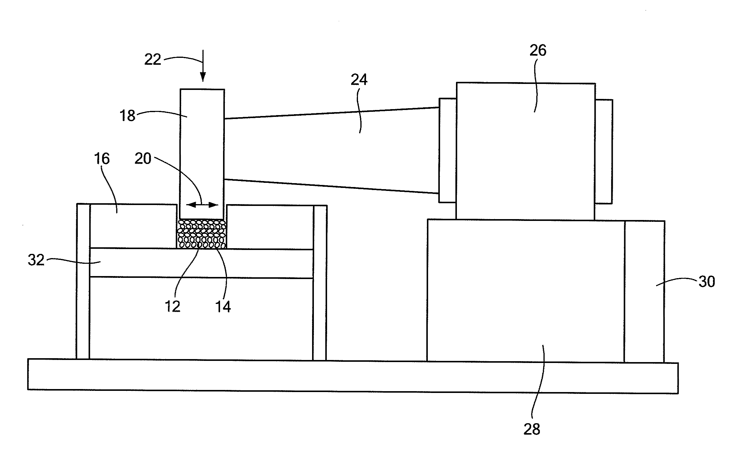
Vibratory powder consolidation
a technology of vibrating powder and consolidated materials, which is applied in the direction of mechanical vibration separation, manufacturing tools, shaping presses, etc., can solve the problems of limiting mechanical properties, posing design constraints, and affecting the microstructure of consolidated materials, and all high-performance materials produced by p/m routes, such as rapid solidification processing alloys and metal-matrix composites (mmc), suffer from structural degradation. , the effect of reducing the cost and reducing the structural degradation
- Summary
- Abstract
- Description
- Claims
- Application Information
AI Technical Summary
Benefits of technology
Problems solved by technology
Method used
Image

Examples
example
[0036]Compacts of Al powder were processed using several routes, as follows:[0037]1) ultrasonic vibrations at room temperature;[0038]2) ultrasonic vibrations at room temperature and subsequent heat treatment at 573 K;[0039]3) ultrasonic vibrations at room temperature and subsequent impact loading at room temperature;[0040]4) ultrasonic vibrations at room temperature and subsequent impact loading at 573 K;[0041]5) ultrasonic vibrations at 573 K; and[0042]6) warm pressing at 573 K (control route).
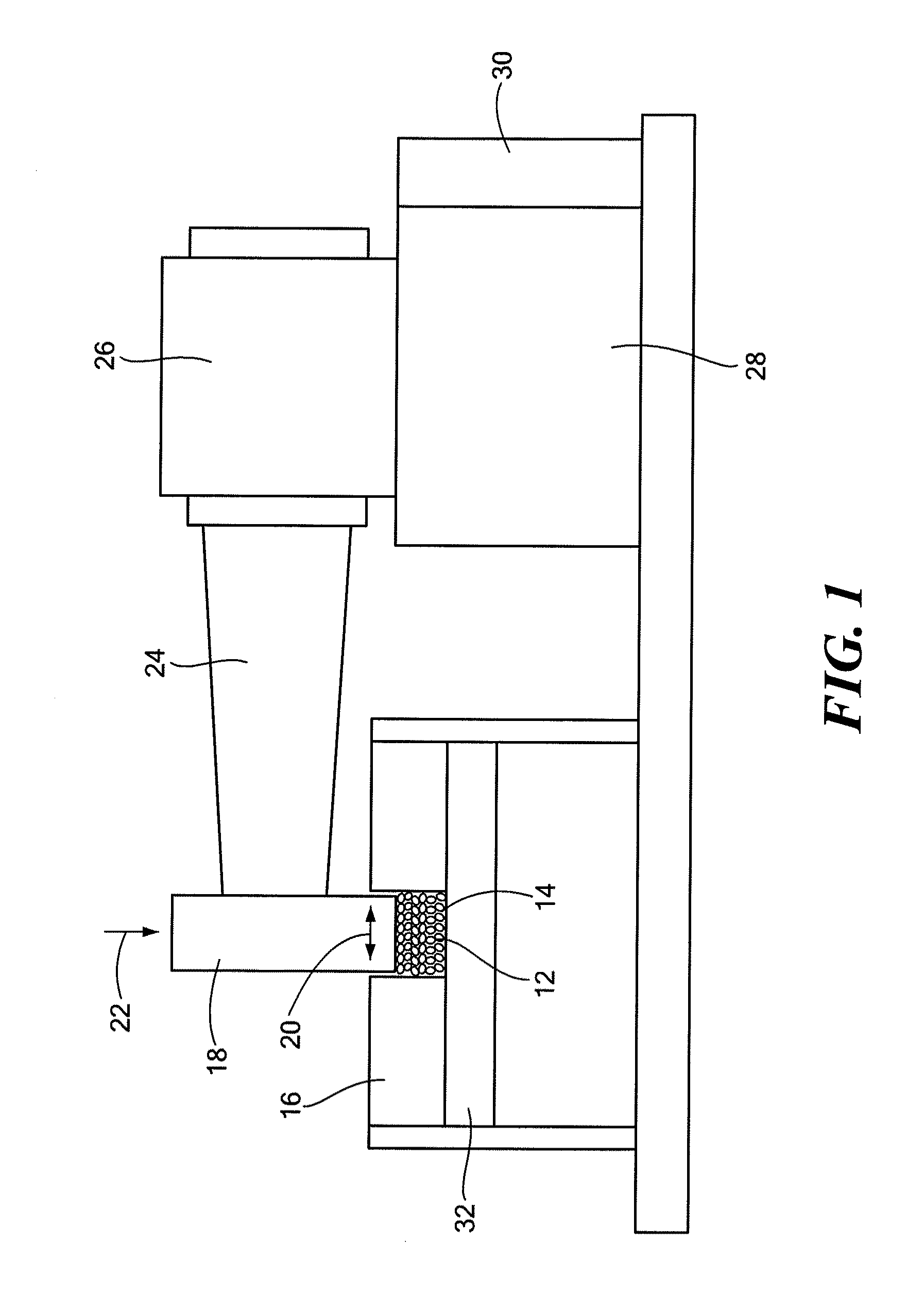
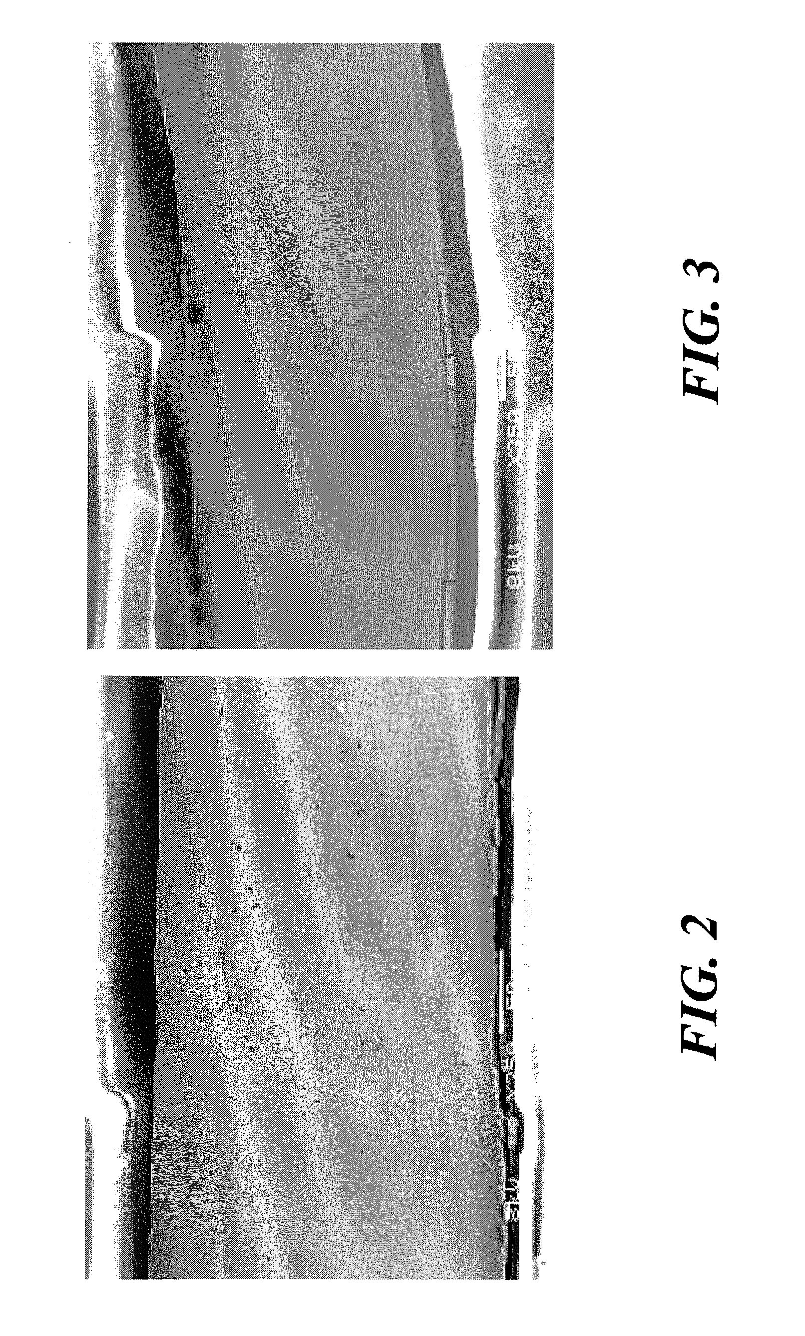
[0043]The Al powder, of 99.5% purity, ˜325 mesh, had an average particle size of 7 to 15 μm. For processing routes 1-5, ultrasonic vibrations were applied at a vibration amplitude of 10 μm and durations of 0.05 s and 1 s and normal loadings of ˜100-200 MPa, up to a maximum normal loading of 320 MPa. Processing routes 1, 2, 3, 4, and 5 resulted in fully dense compacts, whereas the control sample from route 6 remained porous.
[0044]FIG. 2 shows the microstructure of a compact processed by the co...
PUM
| Property | Measurement | Unit |
|---|---|---|
| Length | aaaaa | aaaaa |
| Time | aaaaa | aaaaa |
| Frequency | aaaaa | aaaaa |
Abstract
Description
Claims
Application Information