
Fuel cell and fuel cell system including the same

a fuel cell and system technology, applied in the field of fuel cell and fuel cell system, can solve the problems of increasing the ratio of empty spaces in the separator, reducing the strength of the separator, and affecting the operation of the separator, so as to achieve the effect of simple configuration

Inactive Publication Date: 2010-01-07
PANASONIC CORP
View PDF2 Cites 11 Cited by
  • Summary
  • Abstract
  • Description
  • Claims
  • Application Information

AI Technical Summary

Benefits of technology

The present invention relates to a fuel cell and a fuel cell system that can quickly and efficiently detect even minor damage to the fuel cell stack, such as damage caused by impact or damage to the gas channels or inner membrane. The invention includes a fuel cell with a unique configuration that includes damage detecting wires formed at components of the fuel cell, such as the electrolyte layer-electrode stack assembly, the separator, and the gas channels. The damage detecting wires are connected to each other to form an open circuit by stacking the cells. This allows for quick detection of damage to the fuel cell stack without the need for an excessive additional device. The technical effect of the invention is to provide a fuel cell and system that can quickly and accurately detect damage to the fuel cell stack, thereby improving operational efficiency and preventing damage to the fuel cell.

Problems solved by technology

However, in a case where the components are efficiently arranged, the ratio of empty spaces in the separator becomes high, and this decreases the strength of the separator.
Therefore, the separator, especially the peripheral portion of each manifold of the separator, tends to be damaged.
Moreover, in a case where the separator is damaged, the fuel cell cannot operate.

Method used


Image

  • Fuel cell and fuel cell system including the same
  • Fuel cell and fuel cell system including the same
  • Fuel cell and fuel cell system including the same

Examples


embodiment 1

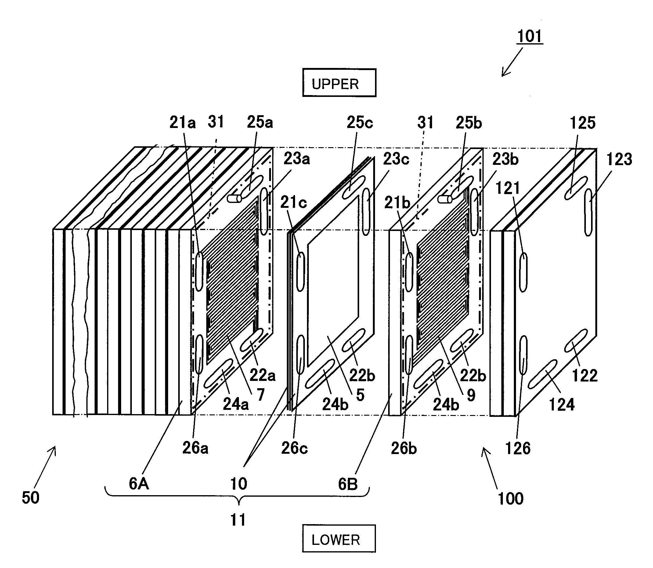
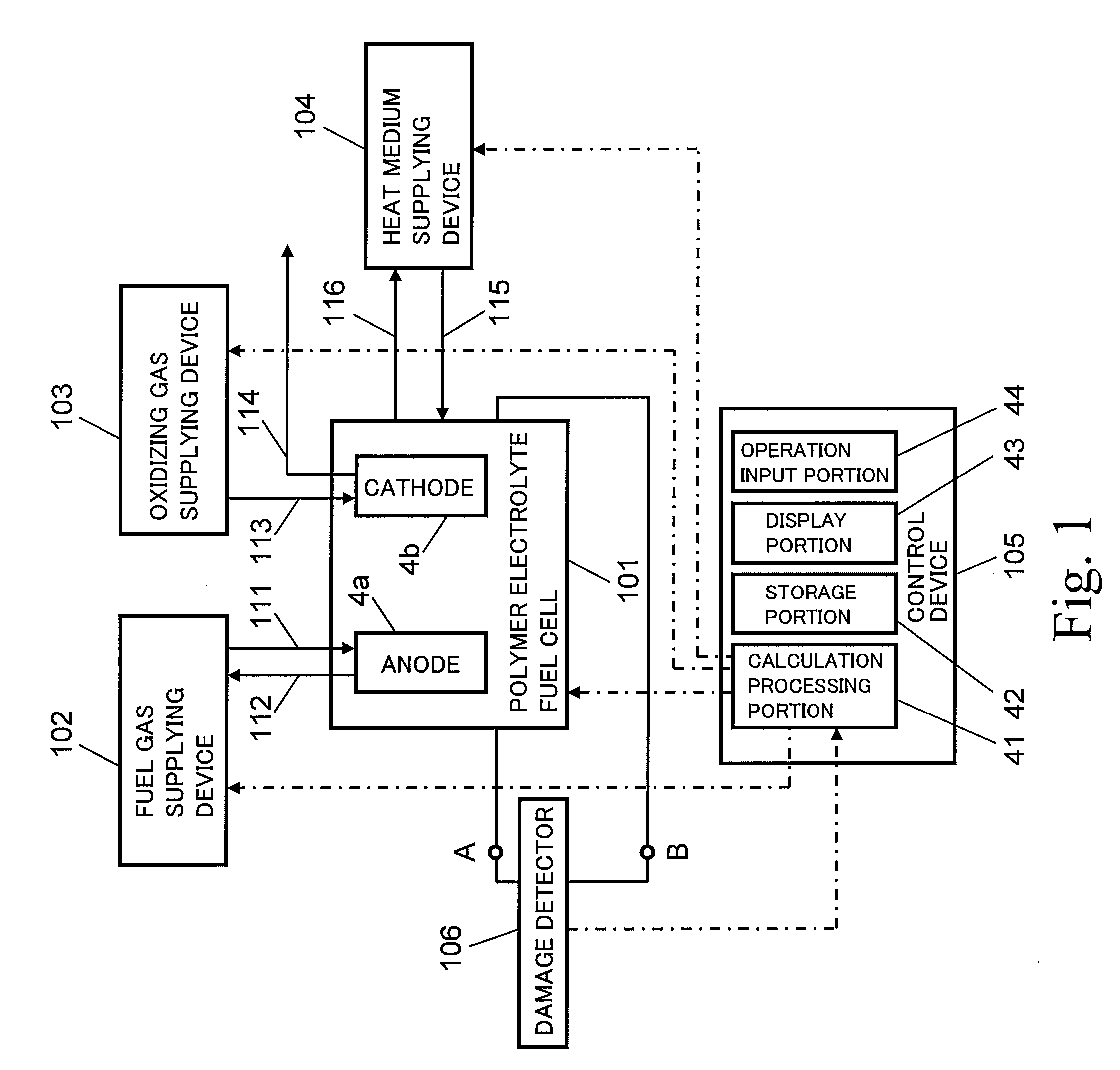
[0127]FIG. 1 is a block diagram schematically showing the configuration of a fuel cell system according to Embodiment 1 of the present invention.

[0128]First, the configuration of the fuel cell system according to Embodiment 1 will be explained.

[0129]As shown in FIG. 1, the fuel cell system according to Embodiment 1 includes a polymer electrolyte fuel cell (hereinafter referred to as “PEFC”) 101, a fuel gas supplying device 102, an oxidizing gas supplying device 103, a heat medium supplying device 104, a control device 105, and a damage detector 106.

[0130]The PEFC 101 is connected to the fuel gas supplying device 102 by a fuel gas supplying passage 111. The fuel gas supplying device 102 supplies a fuel gas to an anode 4a of the PEFC 101 through the fuel gas supplying passage 105. Herein, the fuel gas supplying device 102 includes: a plunger pump (not shown) which feeds a natural gas (material gas), supplied from a natural gas supply infrastructure, to a fuel processor (not shown); a ...

modification example 1

[0185]FIG. 7 is a schematic diagram showing the configuration of the cell 11 in Modification Example 1. FIG. 8 is a cross-sectional view showing a cross section taken along line VI-VI of FIG. 7. In FIGS. 7 and 8, a part of the cell 11 is omitted. In the following explanation, same reference numbers are used for the same or corresponding portions as in FIG. 3, and a repetition of the same explanation is avoided.

[0186]The fuel cell system of Modification Example 1 and the fuel cell system according to Embodiment 1 are the same in the basic configuration as each other. However, the damage detecting wire 31 disposed in the fuel cell stack 100 is different therebetween as follows.

[0187]As shown in FIG. 7, the routing portion 31a of the damage detecting wire 31 is formed on the inner surfaces of the anode separator 6A and the cathode separator 6B so as to project from the inner surfaces of the anode separator 6A and the cathode separator 6B.

[0188]Moreover, as shown in FIG. 8, the first co...

embodiment 2

[0194]The fuel cell system according to Embodiment 2 of the present invention and the fuel cell system according to Embodiment 1 are the same in the basic configuration as each other, but are different from each other as below.

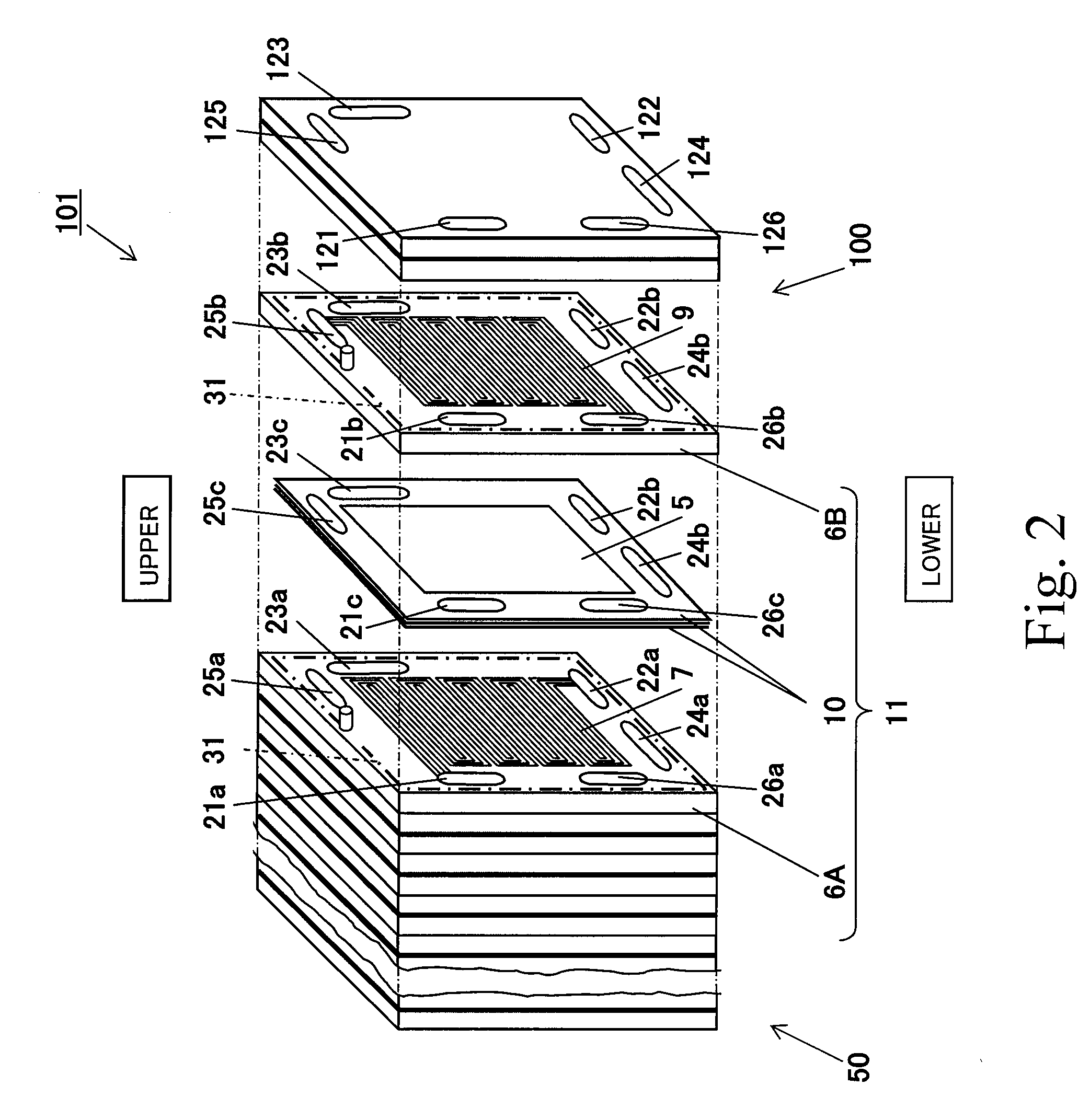
[0195]FIG. 9 is a developed view schematically showing a PEFC 101A of the fuel cell system according to Embodiment 2. Note that a vertical direction in FIG. 9 is defined as shown in the drawing. In the following explanation, same reference numbers are used for the same or corresponding portions as in FIG. 2, and a repetition of the same explanation is avoided.

[0196]As shown in FIG. 9, in the PEFC 101A of the fuel cell system according to Embodiment 2, the routing portion 31a constituting the damage detecting wire 31 is disposed to extend along a side surface (outer peripheral portion) of each of the separators 6A and 6B substantially once. Then, the first connection portion 31b connects the start end portion of the routing portion 31a of the anode separator 6A...


PUM


Abstract

A fuel cell includes: cells (11), each of which includes an electrolyte layer-electrode stack assembly (5) having a electrolyte layer (1) and a pair of gas diffusion electrodes (4a, 4b) sandwiching a portion of the electrolyte layer (1) which portion is located on an inner side of a peripheral portion of the electrolyte layer (1), an annular peripheral member disposed at the peripheral portion of the electrolyte layer (1), a pair of electrically conductive separators (6A, 6B) which sandwich the electrolyte layer-electrode stack assembly (5) and the peripheral member, and damage detecting wires (31); and a fuel cell stack (100) formed by stacking the cells (11), wherein: the damage detecting wires (31) are formed on components constituting the cell (11) other than the electrolyte layer-electrode stack assembly (5); and the damage detecting wires (31) are connected to one another to form an open circuit by stacking the cells (11).

Description

TECHNICAL FIELD[0001]The present invention relates to a fuel cell and a fuel cell system including the fuel cell, and particularly to a configuration of the fuel cell.BACKGROUND ART[0002]A fuel cell cause a hydrogen-containing fuel gas, which is obtained by reforming a material gas, such as a city gas, and an oxidizing gas, such as air, containing oxygen to electrochemically react with each other, thereby generating electric power and heat at the same time. A unit cell (cell) of the fuel cell includes: an electrolyte layer-electrode stack assembly constituted by a electrolyte layer and a pair of gas diffusion electrodes; gaskets; and electrically conductive separators. A groove-like gas channel through which the fuel gas or the oxidizing gas (each of which is called a reactant gas) flows is formed on a main surface of each separator which surface contacts the gas diffusion electrode. The gaskets are disposed on peripheral portions of the electrolyte layer-electrode stack assembly, a...

Claims


Application Information

Patent Timeline
Patent Type & Authority Applications(United States)
IPC IPC(8): H01M8/10
CPCH01M8/02H01M8/0202H01M8/0267H01M8/0273H01M8/0276H01M8/04671Y02E60/50H01M8/04731H01M8/04753H01M8/04992H01M8/242H01M8/2465H01M2008/1095H01M8/04679H01M8/2483H01M8/2457H01M8/0263H01M8/0258
Inventor SUGAWARA, YASUSHITAKAYUKI, URATAMORITA, JUNJISHIBATA, SOICHIUMEDA, TAKAHIRO
Owner PANASONIC CORP
Learn More