
High shear rotary fixed bed reactor

a fixed bed reactor and high shear technology, applied in chemical/physical/physical-chemical stationary reactors, chemical/physical processes, beer fermentation, etc., can solve the problems of unsuitability of fixed bed operation, the use of small sized solid catalyst particles in slurry reactors and fixed bed reactors, and the control of reaction rate, so as to reduce catalyst usage, reduce costs, and increase fluid throughput

Inactive Publication Date: 2010-01-07
HRD CORP
View PDF19 Cites 34 Cited by
  • Summary
  • Abstract
  • Description
  • Claims
  • Application Information

AI Technical Summary

Benefits of technology

[0017]Certain embodiments of the above-described methods or systems potentially provide overall cost reduction by providing for reduced catalyst usage, permitting increased fluid throughput, permitting operation at lower temperature and / or pressure, and / or reducing capital and / or operating costs. These and other embodiments and potential advantages will be apparent in the following detailed description and drawings.

Problems solved by technology

In cases where it is desirable to react two or more raw materials of different phases (e.g. solid and liquid; liquid and gas; solid, liquid and gas), one of the limiting factors controlling the rate of reaction involves the contact time of the reactants.
In the case of heterogeneously catalyzed reactions there is the additional rate limiting factor of having the reacted products removed from the surface of the solid catalyst to permit the catalyst to catalyze further reactants.
The use of small sized solid catalyst particles in slurry reactors and fixed bed reactors presents problems.
For example, in instances where the reaction to be catalyzed is highly exothermic (e.g., Fischer-Tropsch conversion of gases to liquid hydrocarbons), fixed bed operation may be unsuitable due to the inability to adequately control the reactor temperature.
Slurry operation may overcome the temperature control issue, but concomitantly presents the issue of separating the small catalyst particles from the product prior to recycle, disposal and / or regeneration of the catalyst and sale or further processing of the product.

Method used


Image

  • High shear rotary fixed bed reactor
  • High shear rotary fixed bed reactor
  • High shear rotary fixed bed reactor

Examples


Embodiment Construction

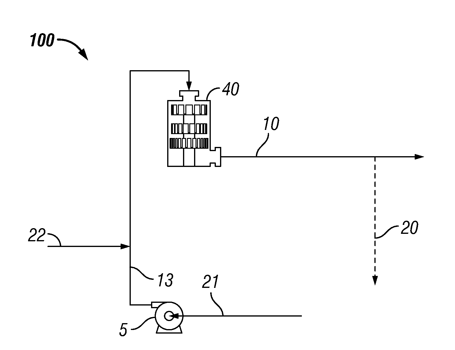
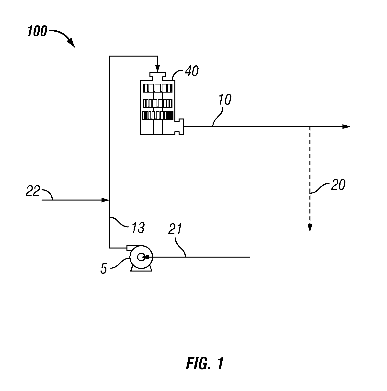
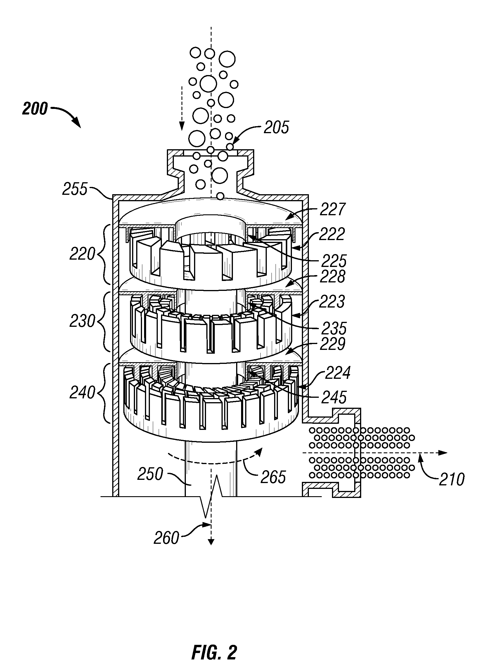
[0029]Overview. A system and process for catalytic reaction utilizing high shear contacting of reactants with a rotating structure comprising solid catalyst comprises an external high shear mechanical device to provide rapid contact and mixing of reactants in a controlled environment in the reactor / mixer device. A reactor assembly that comprises an external rotary fixed bed (RFB) or mixer as described herein may decrease mass transfer limitations and thereby allow the catalytic reaction to more closely approach kinetic limitations. Enhanced mixing may also homogenize the temperature within the reaction zone(s). Enhancing contact via the use of high shear may permit increased throughput and / or the use of a decreased amount of catalyst relative to conventional processes.

[0030]Other uses of the disclosed system and method will become apparent upon reading the disclosure and viewing the accompanying drawings. While specific examples may be presented in the following description, other e...


PUM

PropertyMeasurementUnit
Lengthaaaaaaaaaa
Lengthaaaaaaaaaa
Lengthaaaaaaaaaa

Abstract

A reactor comprising at least one contact surface made from, coated with, or impregnated by a catalyst, wherein the contact surface comprises a sintered metal or a ceramic, and wherein the reactor is configured to subject a reactant stream to shear. A system for carrying out a heterogeneously catalyzed reaction, the system comprising a reactor as described above and a pump configured for delivering reactants to the at least one reactor. A method for carrying out a heterogeneously-catalyzed reaction by introducing reactants into a reactor comprising at least one contact surface made from, coated with, or impregnated by a catalyst under conditions which promote production of a desired product, wherein the contact surface comprises a sintered metal or a ceramic, and forming a dispersion of reactants within the reactor, wherein the dispersion comprises droplets or gas bubbles of reactant with an average diameter of less than about 5 μm.

Description

CROSS-REFERENCE TO RELATED APPLICATIONS[0001]This application claims the benefit under 35 U.S.C. §119(e) of U.S. Provisional Patent Application No. 61 / 078,132, filed Jul. 3, 2008, the disclosure of which is hereby incorporated herein by reference.STATEMENT REGARDING FEDERALLY SPONSORED RESEARCH OR DEVELOPMENT[0002]Not Applicable.BACKGROUND[0003]1. Technical Field[0004]The present invention relates generally to heterogeneously catalyzed reactions. More particularly, the present invention relates to an apparatus and process for contacting reactants with a catalyst whereby a desired product is obtained.[0005]2. Background of the Invention[0006]The rate of chemical reactions involving liquids, gases and solids depend on time of contact, temperature, and pressure. In cases where it is desirable to react two or more raw materials of different phases (e.g. solid and liquid; liquid and gas; solid, liquid and gas), one of the limiting factors controlling the rate of reaction involves the con...

Claims


Application Information

Patent Timeline
IPC IPC(8): C08F110/06C07C53/00C07C45/00C07C49/00B01J19/18C08F110/02
CPCB01F7/00766B01F7/00791C12C11/02C07C2101/16B01F13/1013B01F13/1016B01J8/20B01J8/22B01J10/007B01J14/005B01J19/008B01J19/1806B01J2219/00105C07C29/04C07C29/106C07C45/34C07C45/39C07C51/265C07C67/08C07C209/36C07C31/22C07C31/225C07C35/14C07C31/202C07C31/207C07C31/205C07C47/06C07C49/04C07C49/08C07C63/06C07C69/003C07C211/46C07C211/50C07C69/14C07C2601/16B01F27/2711B01F27/2714B01F33/81B01F33/811B01J2219/1941
Inventor HASSAN, ABBASANTHONY, RAYFORD G.BORSINGER, GREGORYHASSAN, AZIZBAGHERZADEH, EBRAHIM
Owner HRD CORP
Learn More