Driving control of a reciprocating cpr apparatus

Inactive Publication Date: 2010-01-07
PHYSIO CONTROL INC
View PDF15 Cites 41 Cited by
  • Summary
  • Abstract
  • Description
  • Claims
  • Application Information

AI Technical Summary

Benefits of technology

[0021]The contactless method of the invention and the corresponding means thus allow to monitor the position of the compression pad over time, such as over one or several compression cycles. In an reciprocating CPR apparatus with a pre-set compression depth by use of a physical Compression Depth limiter it is possible to monitor the moment at which, or whether, the Compression Depth is reached by an electrical contact mounted at or in proximity of the limiter, which is actuated b

Problems solved by technology

Shallow compressions may be insufficient to restore circulation and oxygenation while compressions that are too deep may damage the ribs and the soft tissues of the chest.
A problem with CPR apparatus d

Method used


Image

  • Driving control of a reciprocating cpr apparatus
  • Driving control of a reciprocating cpr apparatus
  • Driving control of a reciprocating cpr apparatus

Examples


Example

Example 1

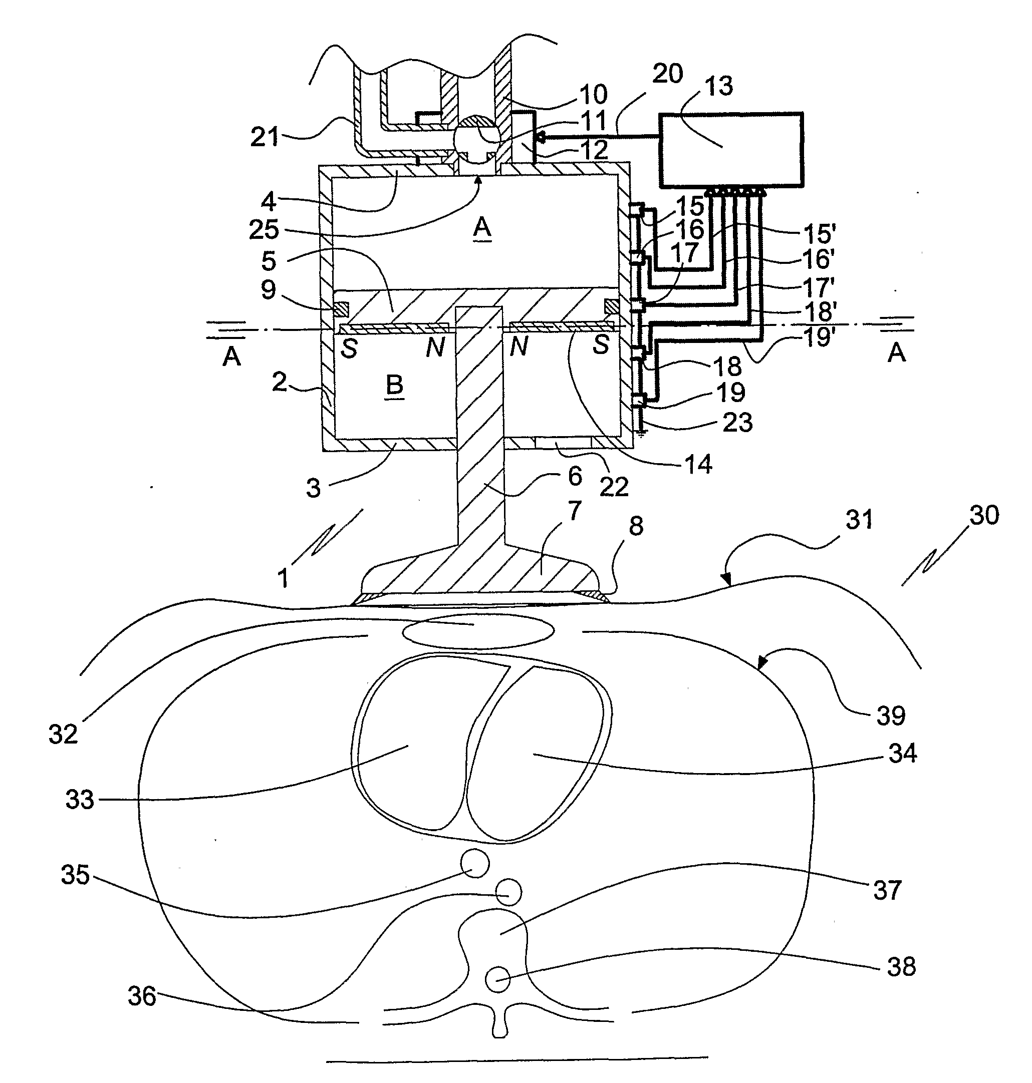
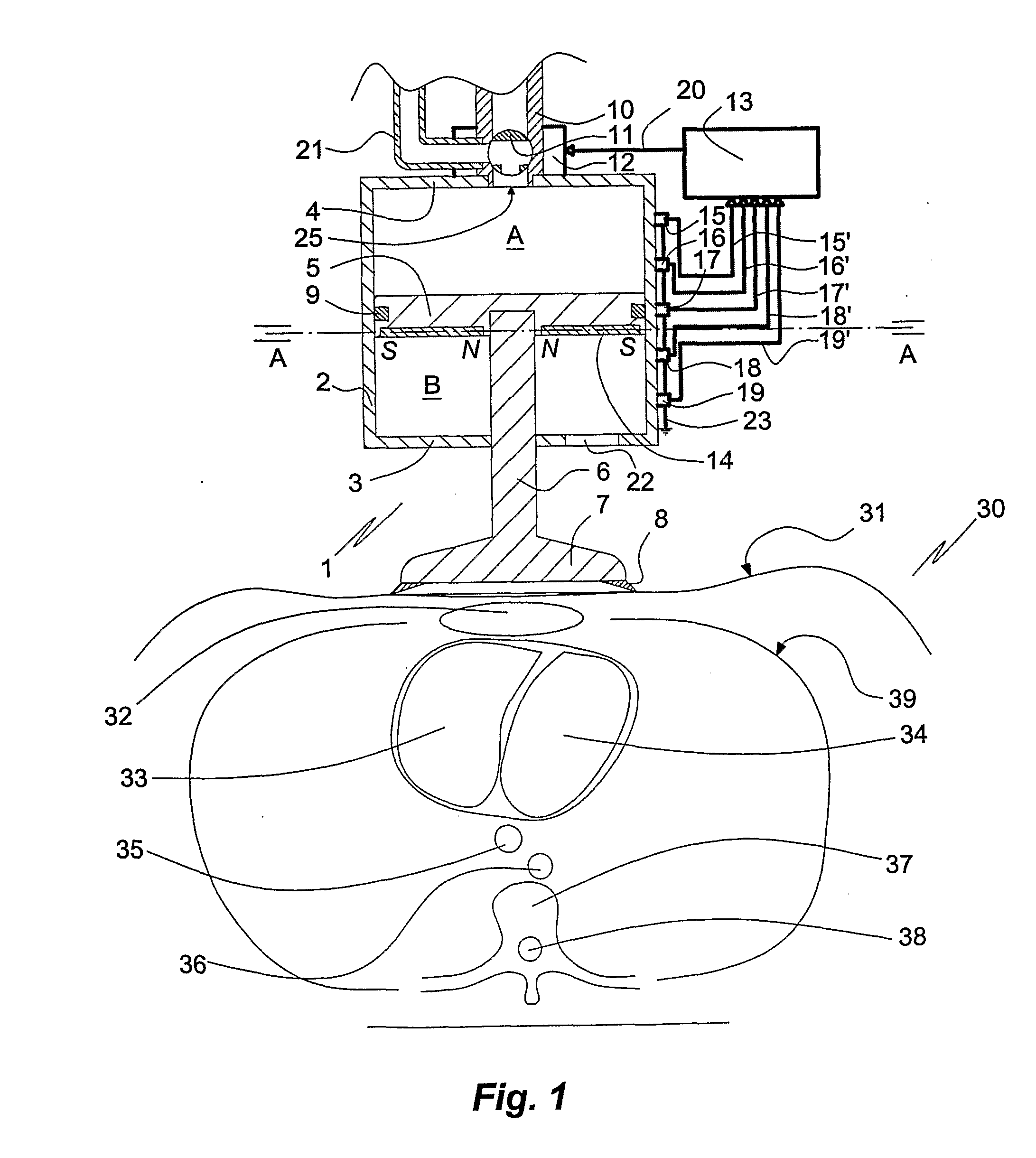
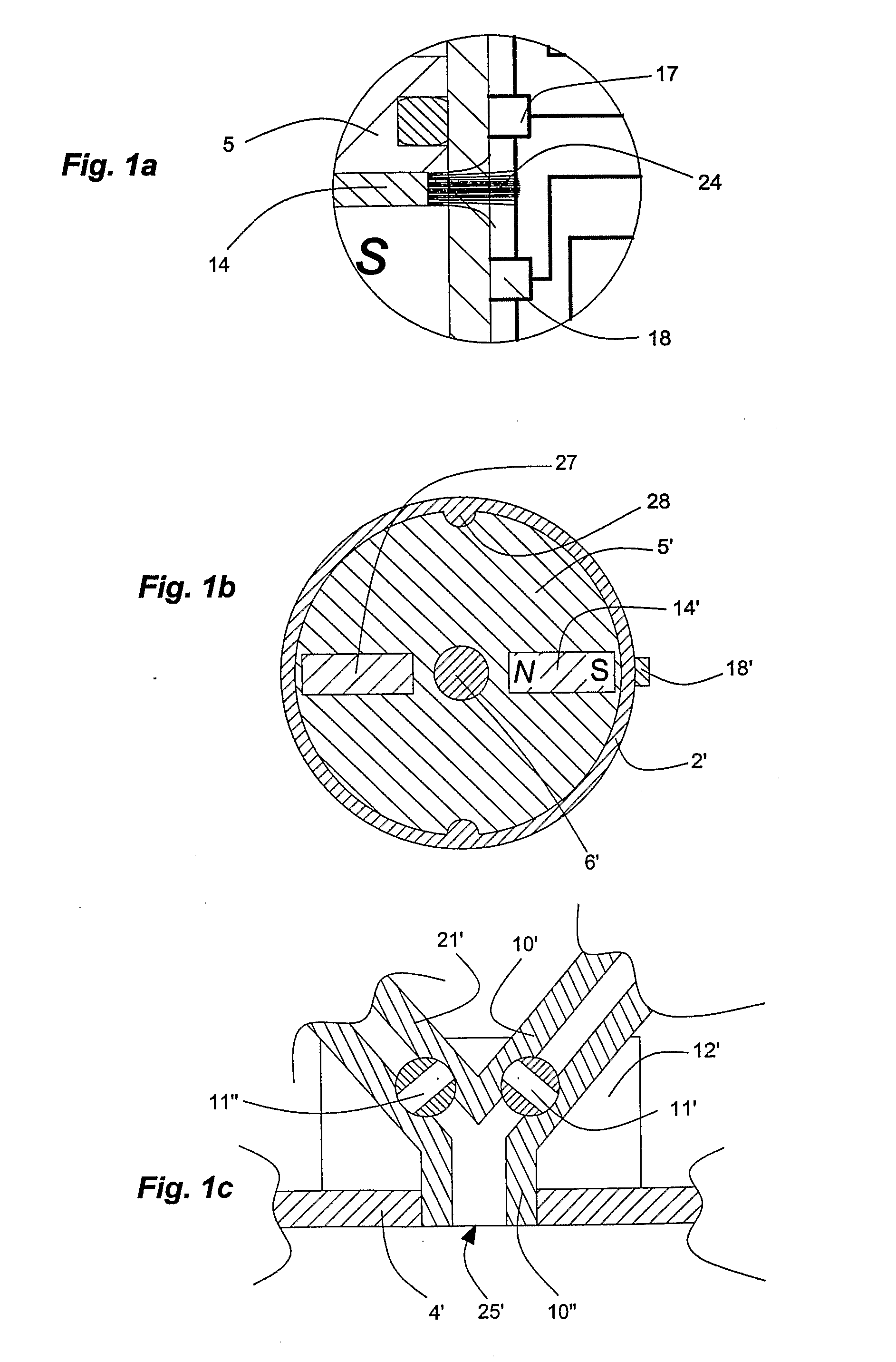
[0045]The embodiment of the apparatus 1 of the invention shown in FIGS. 1-2h comprises a cylinder housing of a diamagnetic material having a side wall 2, a bottom 3 and a top wall 4. A piston 5 with a circumferential sealing 9 is mounted in the housing and defines an upper compartment A and a lower compartment B. A plunger 6 extends downwards from the centre of the piston 5, passing through a central bore in the bottom 3 of the housing. At its free end the plunger 6 carries a chest compression pad 7 provided with a flexible circumferential lip 8. The piston 5 / plunger 6 / compression pad 7 is mounted displaceably in the cylinder housing. A neodymium magnet ring 14 is mounted at the lower face of the piston 5 with its south pole S facing the side wall 2. An array of unipolar Hall-Effect digital switches (“unipolar Hall switches”) 15, 16, 17, 18, 19 is mounted at the outer wall of the cylinder 1 in an axial direction. The unipolar Hall switches 15, 16, 17, 18, 19 are characteriz...

Example

Example 2

Solenoid Valve Control Program

[0057]In the following an example of a simple main valve control program is provided (Table 1). In the example consideration is given to one Hall effect element (Hall switch), which is placed at about a desired level of piston 5 / plunger 6 / rod 7 assembly stop (bottom level). Time open for the decompression main valve is set to 300 ms; while this parameter is fixed in the Example, it could be controlled in precisely the same way as time open for the compression main valve.

TABLE 1Initialize:sett_open = 300[ms]setadjust = true(Parallel process #1, controls main valves)While true dois_down = falsemain_valve_comp = true / opens compression main valvewaitt_open / holds main valve open for t_open msmain_valve_comp = false / closes compression main valvewait300 - t_open / wait the rest of the compressionphasemain_valve_decomp = true / opens decompression main valvewait300 / waits until whole cycle is completemain_valve_decomp = false / closes decompression main valve...

Example

Example 3

[0059]The effect of the method of the invention in the control of compressed driving gas is demonstrated by three experiments illustrated in FIGS. 5a-5c. The experiments were carried out with an air-driven reciprocating CPR device mounted on a test bench. The CPR apparatus comprises a compression cylinder 208 comprising an upper compartment 219 and a lower compartment 220 delimited in respect of each other by a piston 216 arranged displaceably in the cylinder 208. The apparatus further comprises a breast compression pad 210 attached to the piston 216 via a shaft 211, a valve control unit 212 with a valve manifold, and a gas line 213 supplying driving gas from source of compressed gas (not shown) to the compression cylinder via the valve control unit 212. The stroke (str) of the piston 216 is limited to 55 mm by means of upper 217 and lower 218 stroke limiters disposed in the upper and lower compartments, 219, 220, respectively. The gas pressure in the upper compartment 219 ...


PUM


Abstract

A method of controlling the amount of compressed gas used for driving a reciprocating apparatus for cardio-pulmonary resuscitation (CPR) comprising a valve means for controlling the provision of driving gas comprises operation of the valve means during the compression phase to stop provision of driving gas, which operation is separated in time from the venting of the driving gas from the apparatus at the end of the compression phase. Also disclosed are; a CPR apparatus operated by the method; a method of compression depth sensing.

Description

FIELD OF THE INVENTION[0001]The present invention relates to a method of sensing the chest compression depth in a reciprocating apparatus for cardio-pulmonary resuscitation (CPR) driven by a compressed gas, a method of controlling the amount of compressed gas used for driving a reciprocating apparatus for cardiopulmonary resuscitation (CPR), and a correspondingly operated reciprocating CPR apparatus.BACKGROUND OF THE INVENTION[0002]In cardio-pulmonary resuscitation (CPR) repeated compressions are administered by hand or by apparatus to the chest of the person being resuscitated to maintain circulation and oxygenation of blood. Concomitant with the compressions electrical shocks are provided to the patient to make the heart beat again. Gas-driven reciprocating CPR apparatus have been known in the art and used in practice for a long time; see, for instance, U.S. Pat. Nos. 3,209,747 (Guentner) and 3,277,887 (Thomas). Providing compressions of correct depth is an important factor for su...

Claims


Application Information

Patent Timeline
IPC IPC(8): A61H31/00
CPCA61H31/006A61H2201/1246A61H2201/5007A61H2201/5092A61H2201/5066A61M16/00A61H2201/1664A61H2201/5064
Inventor NILSSON, ANDERSSEBELIUS, PETER
Owner PHYSIO CONTROL INC
Why Eureka
Try Eureka