Method for cooling a cryostat configuration during transport and cryostat configuration with transport cooler unit

a technology for cryostats and coolers, which is applied in refrigeration devices, superconducting magnets/coils, lighting and heating apparatus, etc., can solve the problems of large space occupation in laboratories, frequent maintenance of cryostat configurations, and large volume of cryostat configurations, and achieve good thermal contact

Inactive Publication Date: 2010-01-14
BRUKER BIOSPIN
View PDF11 Cites 6 Cited by
  • Summary
  • Abstract
  • Description
  • Claims
  • Application Information

AI Technical Summary

Benefits of technology

[0025]The inventive cryostat configuration is particularly advantageous if a neck tube is provided to contain a cold head of the refrigerator, wherein one end of the neck tube is connected to the outer jacket and its other end is connected to the helium tank, wherein the contact element is disposed inside the neck tube and the stationary section of the contact element makes thermally conductive contact with a cold stage of the cold head during stationary operation and with the liquid nitrogen transported via the supply tube during transport operation. The thermal contact between the radiation shield and the nitrogen is therefore established in the neck tube, which is usually u

Problems solved by technology

However, such configurations require frequent maintenance as the nitrogen tank usually has to be refilled every two weeks due to evaporation of the liquid nitrogen.
However, all cryostat configurations with a nitrogen tank have the disadvantage that the resulting cryostat configuration is very large due to incorporation of the nitrogen tank and therefore occupies a large amount of space in the laboratory.
However, the transport of cryostat configurations in the cold state is a time-critical and expensive undertaking.
Transport by airfreight, although less problematic, is, however, very expensive.
Transport by sea is considerably cheaper but very time consuming.
Since the refrigerator consumes a large amount of electrical energy, it is almost logistically impossible to run it while the cryostat configuration is being transported: The compressor of the cold head requires up to 15 kW of electrical power, a large part of which is converted to heat and u

Method used


Image

  • Method for cooling a cryostat configuration during transport and cryostat configuration with transport cooler unit
  • Method for cooling a cryostat configuration during transport and cryostat configuration with transport cooler unit
  • Method for cooling a cryostat configuration during transport and cryostat configuration with transport cooler unit

Examples


Embodiment Construction

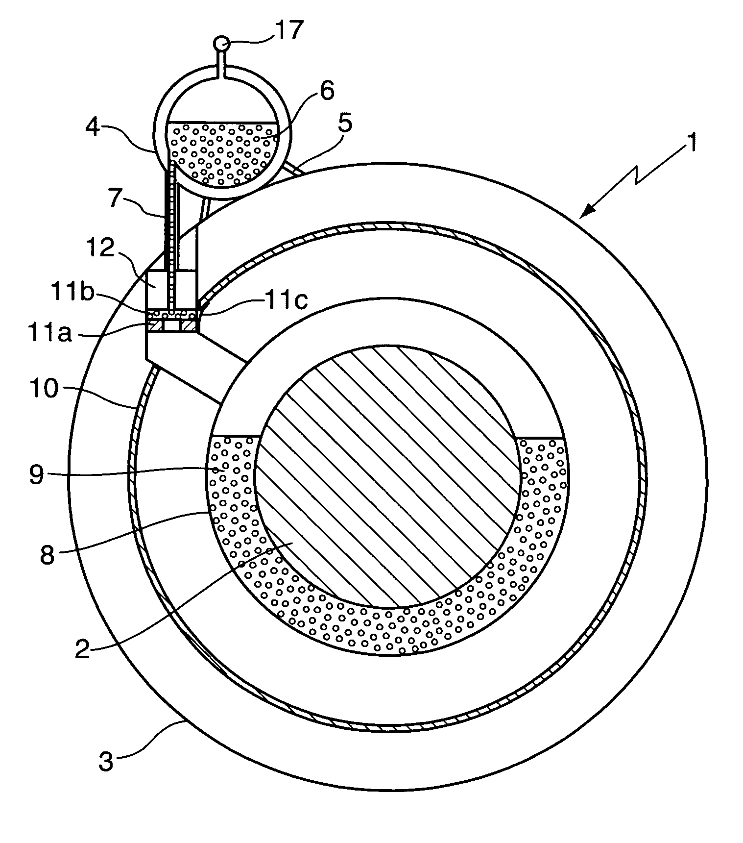
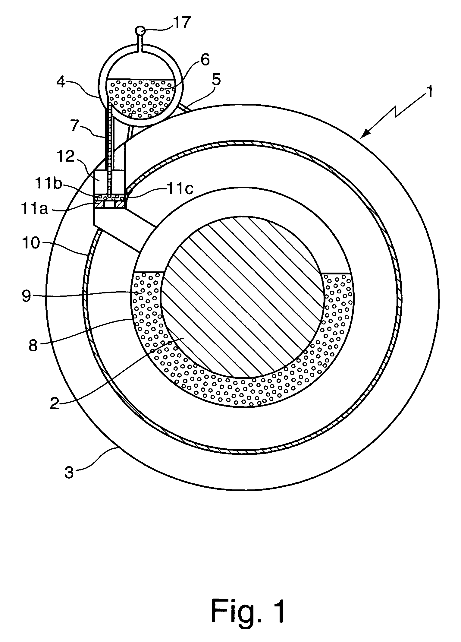
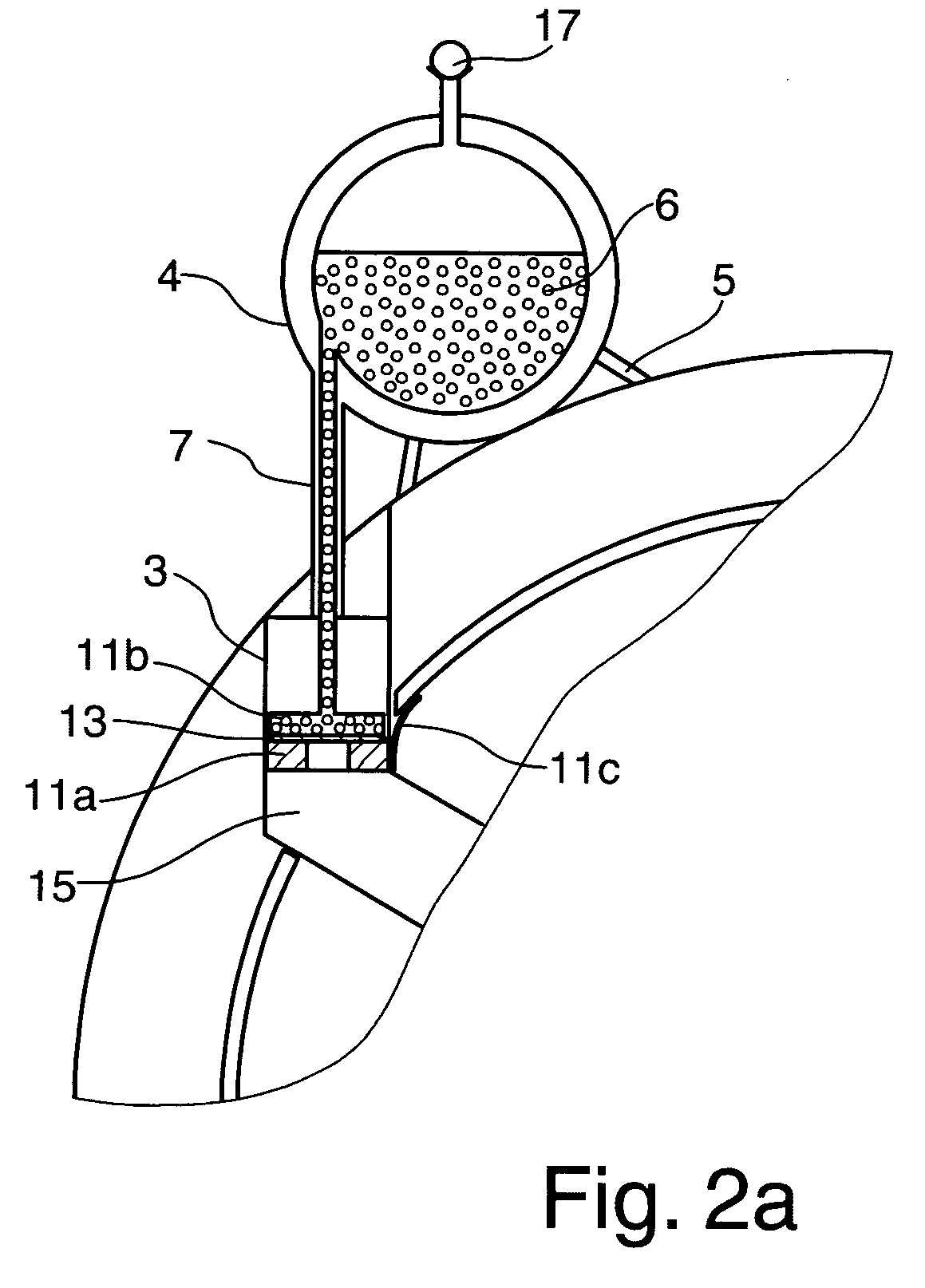
[0038]FIG. 1 shows an inventive cryostat configuration 1 that is suitable for long transport with a cooled superconducting magnet coil 2 without the superconducting magnet coil 2 becoming dry. The cryostat configuration 1 comprises an outer jacket 3 to whose exterior a nitrogen vessel 4 is detachably attached with a fixing facility. In the present example, the fixing facility comprises fixing clip 5 and additional connection elements disposed on the outer shield, such as, for example, thread holes, bolts etc., with which the fixing clip 5 can preferably be detachably connected to the outer shield. Liquid nitrogen 6 can be conveyed to the inside of the cryostat configuration 1 via a supply tube 7.

[0039]The superconducting magnet coil 2 to be cooled is located in helium tank 8 containing liquid helium 9, which is surrounded by a radiation shield 10. A vacuum space is disposed between the radiation shield 10 and the helium tank 8, and between the radiation shield 10 and outer jacket 3....


PUM


Abstract

A method for cooling a cryostat configuration (1, 1′) during transport, wherein the cryostat configuration (1) comprises a superconducting magnet coil (2) in a helium tank (8) containing liquid helium (9), which is surrounded by at least one radiation shield (10), wherein the cooling inside the cryostat configuration (1, 1′) in stationary operation is performed entirely without liquid nitrogen by means of a refrigerator, characterized in that during transport, the refrigerator is switched off and instead, liquid nitrogen (6) is conducted from an external nitrogen vessel (4) via a supply tube (7) from the nitrogen vessel (4) to the cryostat configuration (1, 1′) and brought into thermal contact with the radiation shield (10) by means of a thermal contact element (11) in the cryostat configuration (1, 1′). In this way, the consumption of liquid helium during transport can be greatly reduced and the possible transport time of a charged superconducting magnet configuration increased.

Description

[0001]This application claims Paris Convention priority of DE 10 2008 031 486.2 filed Jul. 3, 2008 the complete disclosure of which is hereby incorporated by reference.BACKGROUND OF THE INVENTION[0002]The invention relates to a method for cooling a cryostat configuration during transport, wherein the cryostat configuration comprises a superconducting magnet coil in a helium tank containing liquid helium, which is surrounded by at least one radiation shield, wherein the cooling inside the cryostat configuration in stationary operation is performed entirely without liquid nitrogen using a refrigerator. The invention also relates to a cryostat configuration with an outer shield within which a helium tank for liquid helium is installed, which contains a superconducting magnet coil and with at least one radiation shield surrounding the helium tank, wherein the cryostat configuration is cooled by a refrigerator entirely without liquid nitrogen during stationary operation.[0003]Such a conf...

Claims


Application Information

Patent Timeline
IPC IPC(8): F25D23/00F25B25/00
CPCF25D3/10H01F6/04F25D19/006F25D16/00F17C3/085F17C13/001F17C13/007F25D3/105
Inventor STROBEL, MARCO
Owner BRUKER BIOSPIN
Why Eureka
Try Eureka