
Aircraft wings having continuously tailored structural strength

a technology of structural strength and wings, applied in the field of structures, can solve problems such as axial tension or skin compression

Active Publication Date: 2010-01-14
THE BOEING CO
View PDF31 Cites 32 Cited by
  • Summary
  • Abstract
  • Description
  • Claims
  • Application Information

AI Technical Summary

Benefits of technology

The patent describes a new way to make an aircraft wing that has strong and smoothly varying strength along its length. This is done by using skin panels that have a stiffer web sandwiched between facesheets. The panels are made by continuously varying the thickness, depth, waveform shape, or wavelength of the web along its length. The panels can be joined together without needing fasteners, which reduces labor and material costs. The wing structure can also be tailored to react to the loads it is subjected to. Overall, this new method allows for a more efficient and effective aircraft wing design.

Problems solved by technology

The disclosed wing skin reacts spanwise bending of the wing, which results in either axial tension or compression of the skin.

Method used


Image

  • Aircraft wings having continuously tailored structural strength
  • Aircraft wings having continuously tailored structural strength
  • Aircraft wings having continuously tailored structural strength

Examples


Embodiment Construction

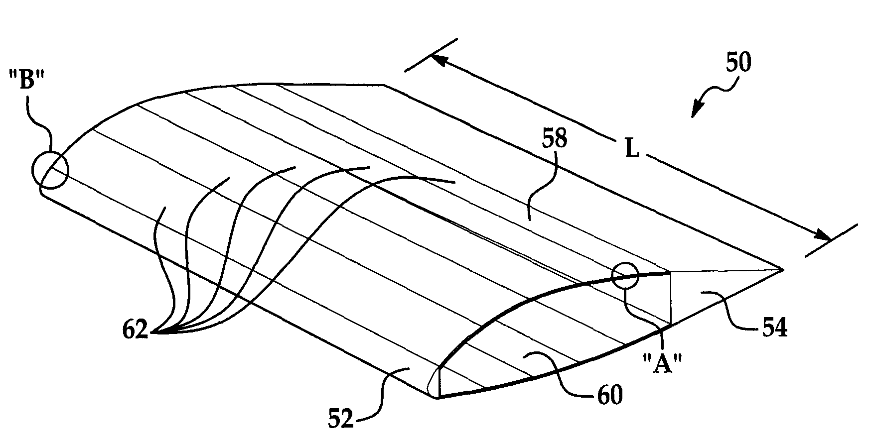
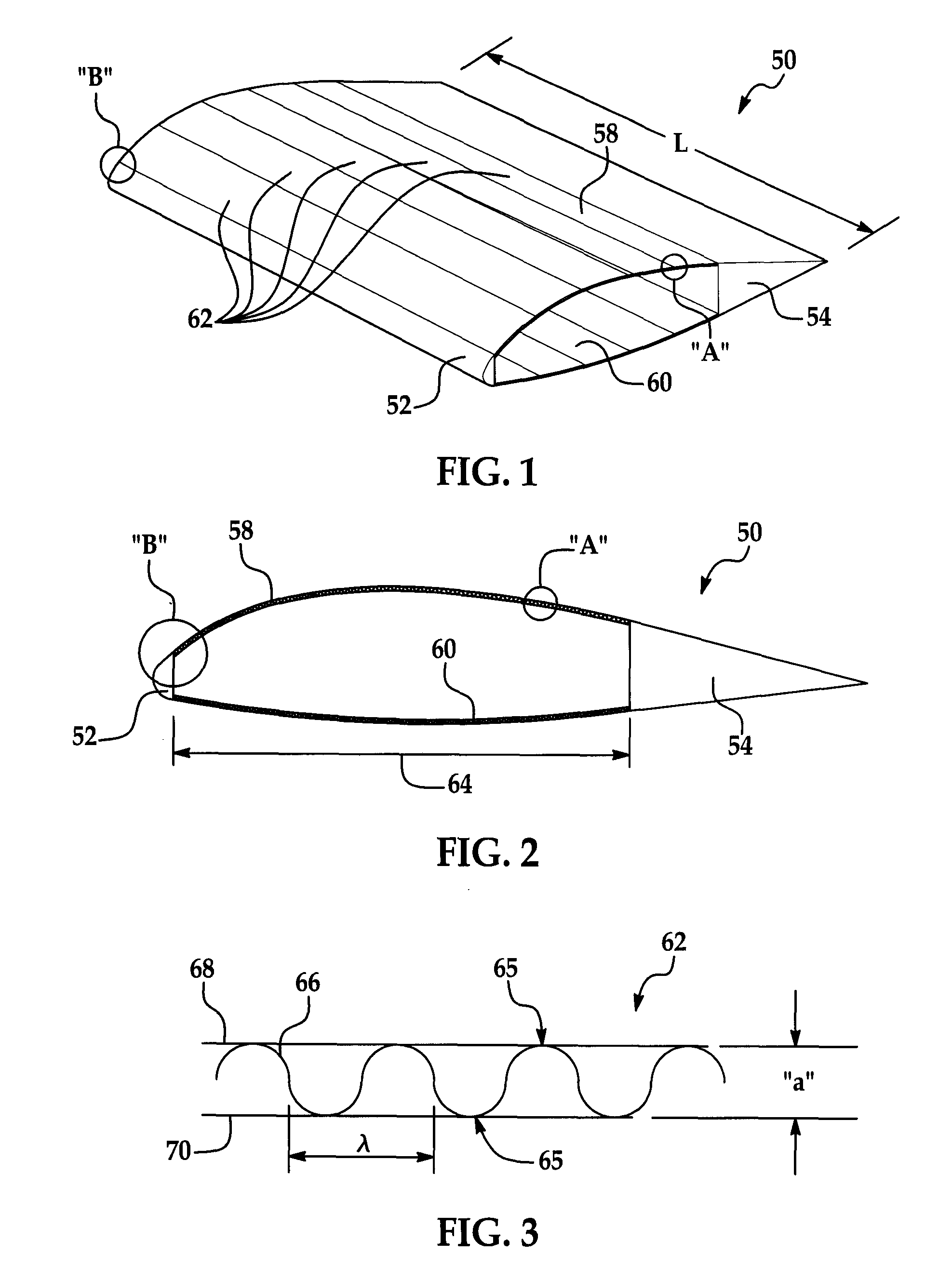
[0013]FIG. 1 is a perspective view of a section of a wing having continuously varying structural strength along its length.

[0014]FIG. 2 is an end view of the wing section shown in FIG. 1.

[0015]FIG. 3 is a cross sectional view of one of a portion of one of the panels forming the wing section shown in FIGS. 1 and 2.

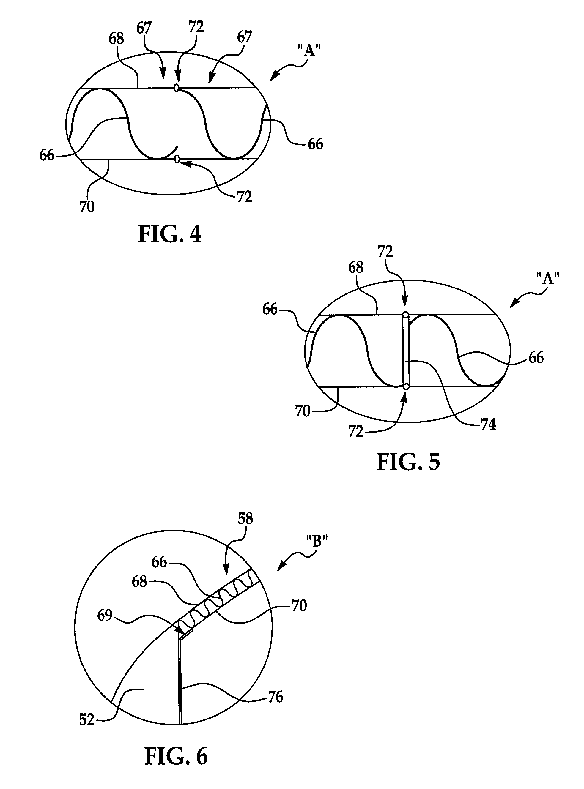
[0016]FIG. 4 is an enlarged view of the area designated as “A” shown in FIGS. 1 and 2.

[0017]FIG. 5 is a view similar to FIG. 4 but showing an alternate embodiment of the skin.

[0018]FIG. 6 is an enlarged view of the area designated as “B” in FIGS. 1 and 2.

[0019]FIGS. 7a-11a are perspective views of alternate embodiments of the web.

[0020]FIGS. 7b-11b are end views of the webs respectively shown in FIGS. 7a-11a.

[0021]FIG. 12 is a diagrammatic view showing wings and horizontal stabilizers of an airplane in which the panels forming the skin are substantially of uniform width.

[0022]FIG. 13 is a view similar to FIG. 12 but showing the use of tapered panels forming a tapered skin....


PUM


Abstract

The structural strength of an aircraft wing is continuously tailored along its length to closely match continuously varying imposed wing loads. The wing comprises upper and lower skins each formed from panels joined together. Each of the skin panels includes a stiffening web sandwiched between and joined to the inner and outer facesheets. The web has a repeating pattern and at least one dimension that continuously varies along the length of the panel.

Description

FIELD OF THE INVENTION[0001]This disclosure generally relates to structures having features tailored to match design loads, and deals more particularly with structures for aircraft such as wings having continuously tailored structural strength along their lengths that more closely match imposed wing loads.BACKGROUND OF THE INVENTION[0002]Certain structures used in aircraft, such as, without limitation, wings, horizontal and vertical stabilizers, fins and the like are often designed to meet or exceed certain design loads. For example, existing metallic wing structures attach a number of discrete, custom manufactured, spanwise stiffeners to thickness tapered skins. The stiffeners and the skin combine at any given buttline cross sectional location to provide at least enough structural material to resist the load on the wing. A maximum number of the stiffeners are used at the wing root where the end load is highest, but the number of stiffeners and / or their thickness is reduced, usually...

Claims


Application Information

Patent Timeline
Patent Type & Authority Applications(United States)
IPC IPC(8): B64C3/00
CPCB64C1/12Y10T428/24694B64F5/0009B64C3/26B64F5/10
Inventor STUHR, VICTORPRICHARD, ALAN KEITHOLIVADOTI, JOSEPH R.
Owner THE BOEING CO
Learn More