Clamp

a technology of clamping and clamping head, which is applied in the field of clamping, can solve the problems of fatigue breakage, difficult cleaning of clamps, and excessive force acting on the deformation area

Active Publication Date: 2010-01-14
KRONES AG
View PDF4 Cites 12 Cited by
  • Summary
  • Abstract
  • Description
  • Claims
  • Application Information

AI Technical Summary

Benefits of technology

[0006]It is the object of the present disclosure to indicate a clamp that, while being of a simple construction, and despite the possibility of compensating for grip width variations of the container, is functionally reliable.
[0007]Owing to the constructional separation between the arm and the gripping arm with its closing lever and thanks to the limited deformation space between the stop on the closing lever and the elastically deformable section, the section is only used for compensating for grip width variations while it is abutting in case of increased forces, and these increased forces are directly transmitted from the closing lever to the closing cam, or vice versa, without any further deformation. Hence, since the section is exempted from the transmission of excessive forces just by way of its elasticity, the average load on the section itself is reduced even in case of a long service life with many operating cycles, so that a fatigue break is almost exclusively ruled out, and the section does not suffer any damage caused by high forces arising in emergency or malfunction situations. This enhances the operational reliability of the clamp considerably. Furthermore, the constructional separation offers the advantage of an inexpensive manufacture and mounting of the clamp, and the clamp can be cleaned easily.
[0008]In an expedient embodiment, the arm is pivotably supported together with the gripping arm about the axis. In combination with the positive coupling, the joint pivotal support has the effect that the arm moves almost as one unit with the gripping arm, and it is only the section of the arm acting on the closing cam that is movable to a limited degree relative to the closing lever to compensate for the grip width variations of the container.
[0010]Expediently, the respective abutment area is block-shaped, so that at both sides of the block large cleaning openings are defined, in which the clamp can be cleaned easily. These cleaning openings can be formed without any constrictions and undercuts.
[0012]Expediently, a thickened support body, which rests on the closing cam, is provided at the free end of the arm so as to achieve a high resistance to wear at that place.
[0017]In an expedient embodiment that permits compact dimensions of the clamp, the bearing lug of the arm has a transverse slot, and the bearing lug of the gripping arm is positioned in the transverse slot.

Problems solved by technology

Since the deformation areas must absorb not only the loads needed for compensating for grip width variations, but must transmit all loads from the closing cam up to the gripping structures, fatigue breaks may occur.
The reason is that excessive forces might act on the deformation area, e.g. when a container to be gripped is misaligned and / or eccentrically stuck due to outside influences, or if another obstacle blocks the closing movement of one or both gripping arms.
Furthermore, a plurality of narrow and undercut cavities are present, so that it is difficult to clean the clamps.
Since every spring assembly is subject not only to deformations for compensating for grip width variations, but must transmit all forces between the closing cam and the gripping arm, fatigue breaks may occur or, in cases of emergency, excessive forces may act on the spring assemblies until these get into abutment, with at least the pressure springs getting easily damaged in this process.

Method used


Image

  • Clamp
  • Clamp
  • Clamp

Examples


Embodiment Construction

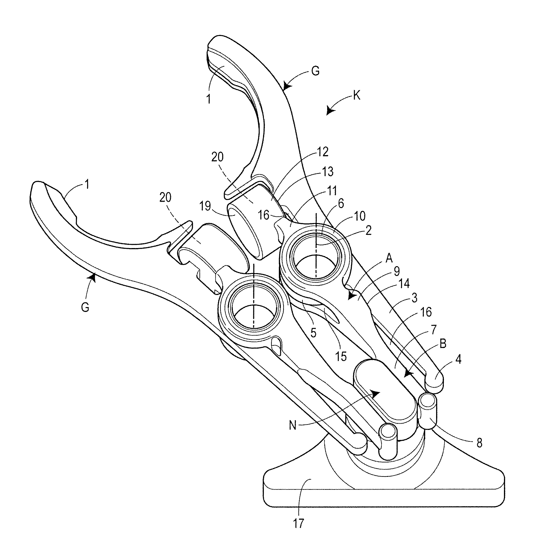
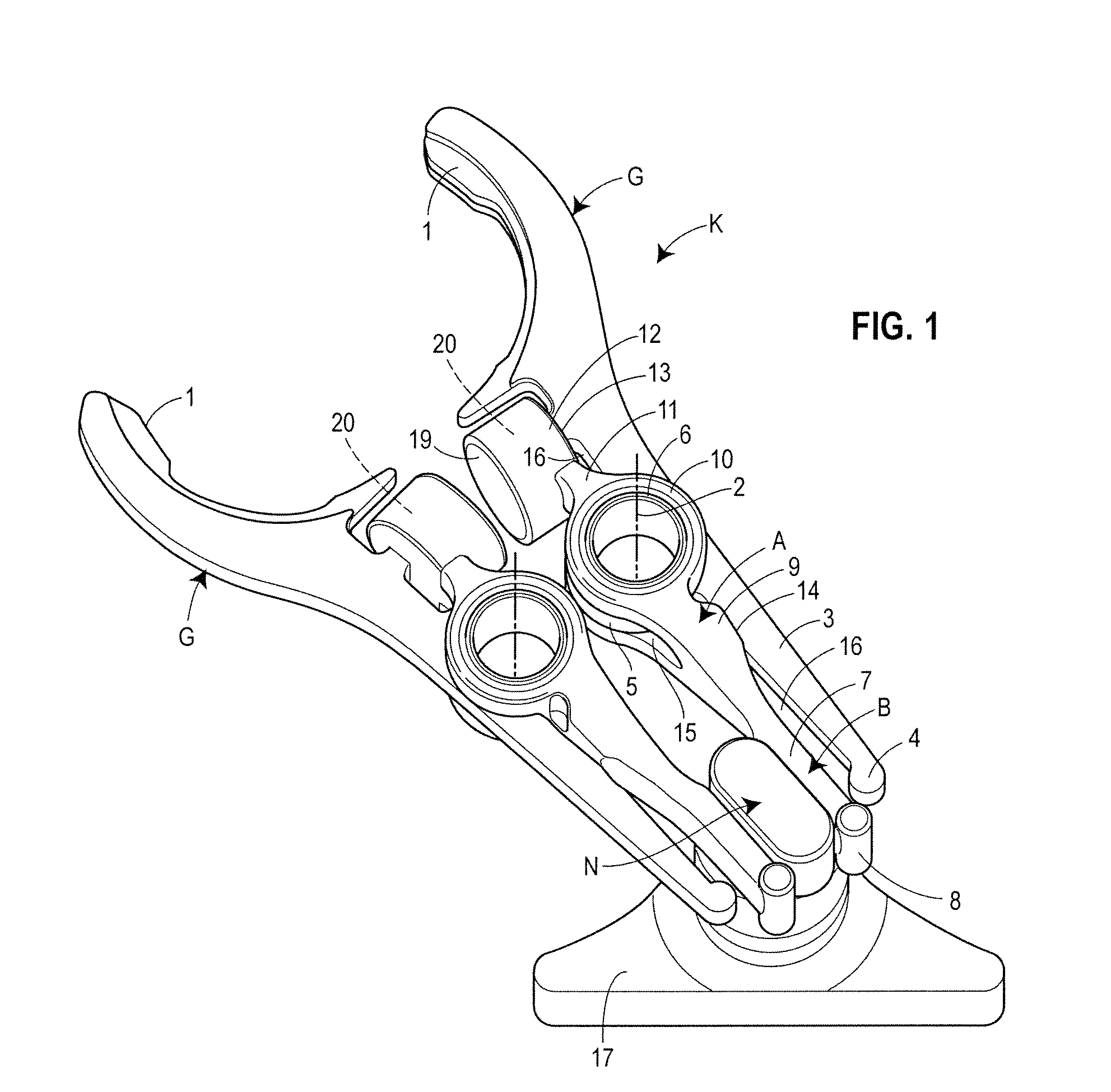
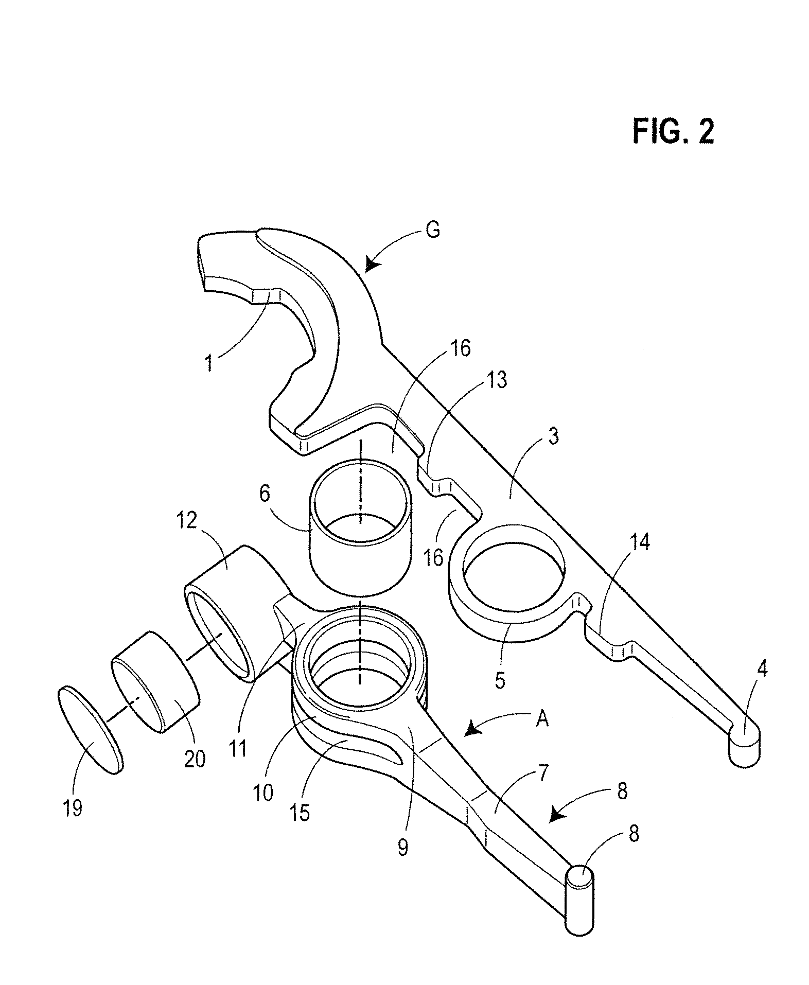
[0024]A clamp K as shown in FIG. 1 for preferably temporarily retaining and positioning a container (not shown), for instance a PET bottle, is arranged in a container treating and transporting apparatus (not shown) on a carrier (not shown). The clamp K comprises two gripping arms G, which are for instance configured as shaped parts of metal and which in the illustrated embodiment are arranged to be pivotable in opposite direction about two separate axes 2. In an alternative (not shown), a joint axis 2 could also be used for the two gripping arms G. Each gripping arm is provided at one end with an inside gripping structure 1 for retaining the container and is extended beyond the axis 2 towards the other axis side with a closing lever 3, the free end of which carries a stop 4 spaced apart from a closing cam N. In the extension of the gripping arm G a bearing lug 5 is formed having a bushing 6 seated therein that pivotably supports the gripping arm G about axis 2.

[0025]Furthermore, at ...


PUM

PropertyMeasurementUnit
elastic deformationaaaaaaaaaa
areaaaaaaaaaaa
abutment areaaaaaaaaaaa

Abstract

A clamp for holding containers, having two rigid gripping arms that are pivotably supported about at least one axis in opposite direction and have clamp structures at one end, a force accumulator which is operative between the gripping arms, gripping-arm closing levers as extensions of the gripping arms towards the other axis side, a closing cam which is rotatable between the closing levers, with at least one closing lever being actuatable by the closing cam via an elastic deformation area, the deformation area is a section of an arm which acts on the closing cam and which is constructionally separated from the gripping arm and which is positively coupled with the gripping arm for joint pivotable movement, and a defined deformation space is provided at least in a substantially undeformed state of the section between a stop on the closing lever and the section.

Description

CROSS-REFERENCE TO RELATED APPLICATION[0001]The present application claims the benefit of priority of German Patent Application No. 102008032923.1, filed Jul. 12, 2008. The entire text of the priority application is incorporated herein by reference in its entirety.FIELD OF THE DISCLOSURE[0002]The present disclosure relates to a clamp such as used for gripping and transporting containers in beverage bottling operations.BACKGROUND[0003]Such clamps are used in large numbers of pieces in container treating or transporting devices so as to temporarily grip and position containers, such as bottles, e.g. PET bottles. A firm seat of the container in the clamp is an important precondition for a smooth operation of the devices. Since the grip width of the containers can vary and since each container must be held independently of the existing grip width in an equally neatly centered way, clamps are used that are controlled between an opened insertion position and a closed gripping position, an...

Claims


Application Information

Patent Timeline
Patent Type & Authority Applications(United States)
IPC IPC(8): B25J15/00B66C1/00B66C1/04B25J15/06
CPCB29C49/4205B65G2201/0247B65G47/847B29C49/42073B29C49/42378B29C49/4238
Inventor GLOTZL, REINER
Owner KRONES AG
Why Eureka
Try Eureka