Supercharge Your Innovation With Domain-Expert AI Agents!

System and method of measuring temperature in a power controller

a technology of power controller and temperature measurement, which is applied in the direction of heat measurement, pulse technique, instruments, etc., can solve the problems of heat dissipation, loss of power provided by solid-state relay, damage to the device, etc., and achieve the effect of reducing the temperature of the solid-state switching device and reducing the power dissipation

Active Publication Date: 2010-01-14
WATLOW ELECTRIC MFG
View PDF7 Cites 12 Cited by
  • Summary
  • Abstract
  • Description
  • Claims
  • Application Information

AI Technical Summary

Benefits of technology

The present invention provides an improved system and method for measuring the temperature of a power controller. The system includes a circuit board, a solid state switching device, a heat sink, and a temperature sensor. The temperature sensor is connected to the circuit board and is in thermal communication with the solid state switching device through the heat sink. The solid state switching device controls the power switching to an industrial load. The temperature sensor can be a temperature sensing leg connected to the trace on the circuit board, or a pad on the circuit board that is in contact with the heat sink. The temperature sensor is in electrical communication with a processor that controls the solid state switching device based on the temperature sensor. The processor can control the solid state switching device to reduce power dissipation and can also control a fan to cool the heat sink. The technical effects of this invention include improved temperature control for power controllers and reduced power dissipation.

Problems solved by technology

Some of the power provided the solid state relay is lost due to voltage drops across the junctions.
Heat generated by the solid state switching device can cause damage to the device if it is not properly dissipated.
However, heat dissipation can be a problem even with a large heat sink.
Further, large heat sinks are often undesirable as they increase the overall cost and package size of the power controller.

Method used


Image

  • System and method of measuring temperature in a power controller
  • System and method of measuring temperature in a power controller
  • System and method of measuring temperature in a power controller

Examples


Embodiment Construction

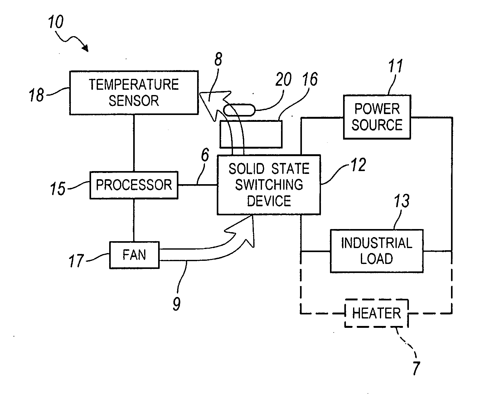
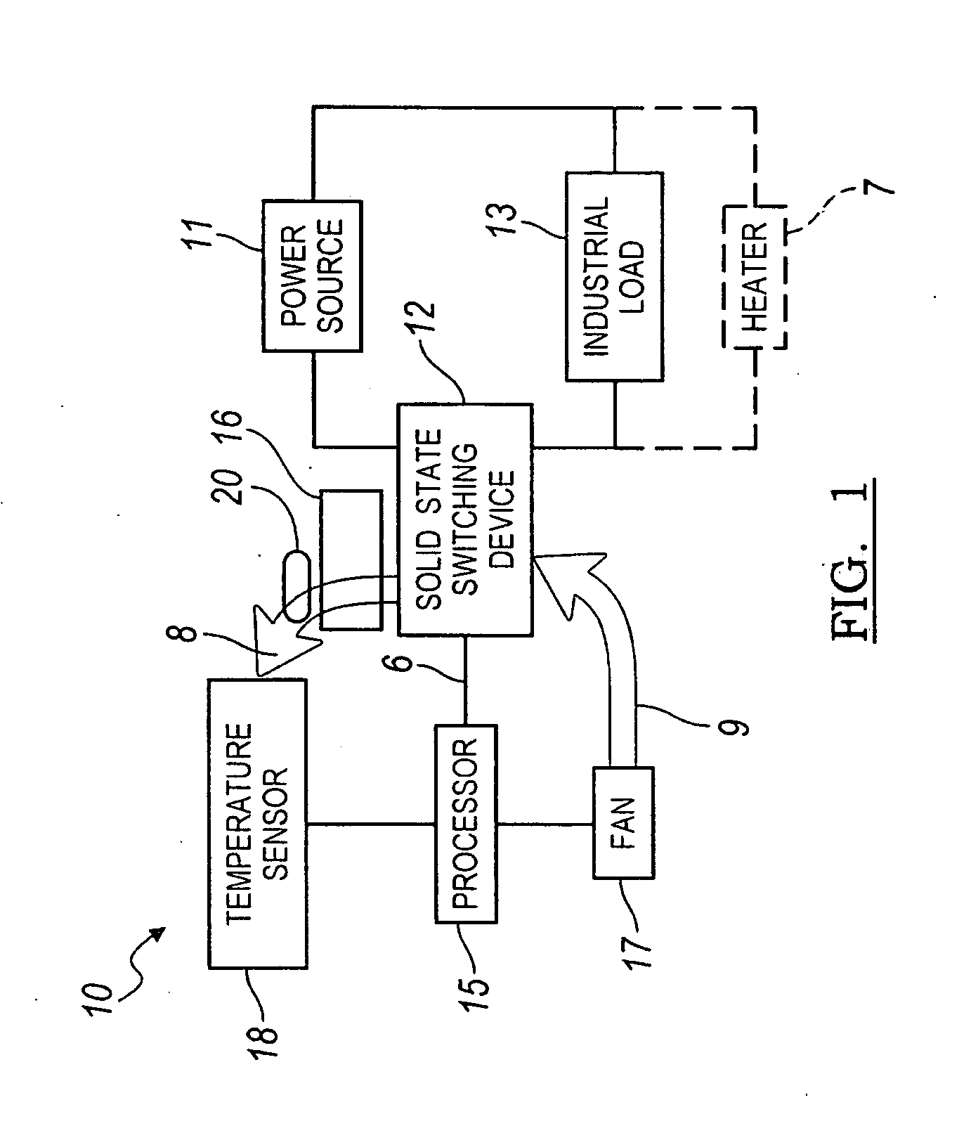
[0018]Referring now to FIG. 1, a system for measuring a temperature in a power controller is illustrated therein and designated at 10. The system 10 includes a solid state switching device 12, a heat sink 16, a trace 20, and a heat sensor 18.

[0019]The solid state switching device 12 is configured to selectively connect a power source 11 to an industrial load 13. Further, the solid state switching device may be configured to provide power to a number of industrial loads in an electrically parallel or series configuration. In one embodiment, the industrial load may be one or more heaters as denoted by reference numeral 7. Heaters are often unique from other industrial loads in that many heating processes can tolerate a slow modification of a temperature, while many other processes require a much faster or instantaneous change in output based on the control signal. A processor 15 provides a control signal 6 to the solid state switching device 12 to change the state of the solid state s...


PUM

PropertyMeasurementUnit
temperatureaaaaaaaaaa
electric poweraaaaaaaaaa
surface areaaaaaaaaaaa

Abstract

An improved system and method measuring a temperature in a power controller is provided. The system includes a circuit board, a solid state switching device, a heat sink, and a temperature sensor. The solid state switching device may be mounted on the circuit board and controls the switching of power to an industrial load. The heat sink is mounted on the solid state switching device such that a first portion of the heat sink is thermal communication with the solid state switching device and a second portion of the heat sink is in thermal communication with an exposed portion of a trace on the circuit board. The temperature sensor may be in thermal communication with the trace. As such, the temperature sensor may be in thermal communication with the solid state switching device through the trace of the circuit board.

Description

BACKGROUND[0001]1. Field of the Invention[0002]The present invention generally relates to a system and method for measuring a temperature in a power controller.[0003]2. Description of Related Art[0004]Power controllers selectively provide power to loads for a number of industrial applications. The power controllers generally use a solid state switching device to allow or interrupt current flow to the industrial load based on a predetermined profile according to time or some other control parameter. Power controllers often switch more than 5 or 10 Amps of current to an industrial load. As electrical current is allowed to flow through the solid state switching device, not all of the current provided to the solid state switching device is ultimately provided to the industrial load. The solid state switching device does not physically disconnect the load from the power source like the contacts of an electromechanical relay. Instead the solid state switching device controls the flow of c...

Claims


Application Information

Patent Timeline
Patent Type & Authority Applications(United States)
IPC IPC(8): H01L35/00G01K13/00H10N10/00
CPCG01K1/16
Inventor NESS, KEITH D.VON ARX, THEODORE T.
Owner WATLOW ELECTRIC MFG
Features
  • R&D
  • Intellectual Property
  • Life Sciences
  • Materials
  • Tech Scout
  • Unparalleled Data Quality
  • Higher Quality Content
  • 60% Fewer Hallucinations
Learn More