
Ionizer

a technology of ionsizers and ions, applied in the field of ionsizers, can solve the problems of falling the removal efficiency of electricity, and achieve the effects of improving the destaticization efficiency, reducing the amount of ions to be neutralized by recombination, and increasing the amount of ions that reach the workpi

Active Publication Date: 2010-01-14
SMC CORP
View PDF5 Cites 13 Cited by
  • Summary
  • Abstract
  • Description
  • Claims
  • Application Information

AI Technical Summary

Benefits of technology

[0007]The object of the present invention, therefore, is to provide an ionizer including discharge electrodes for generating ions and a fan for producing an air flow provided in an air blowing port in a case with an enhanced destaticization efficiency achieved by arranging the discharge electrodes such that the flows of positive and negative ions will not overlap each other to prevent recombination of ions and thus increase the amount of ions to be fed to a workpiece.
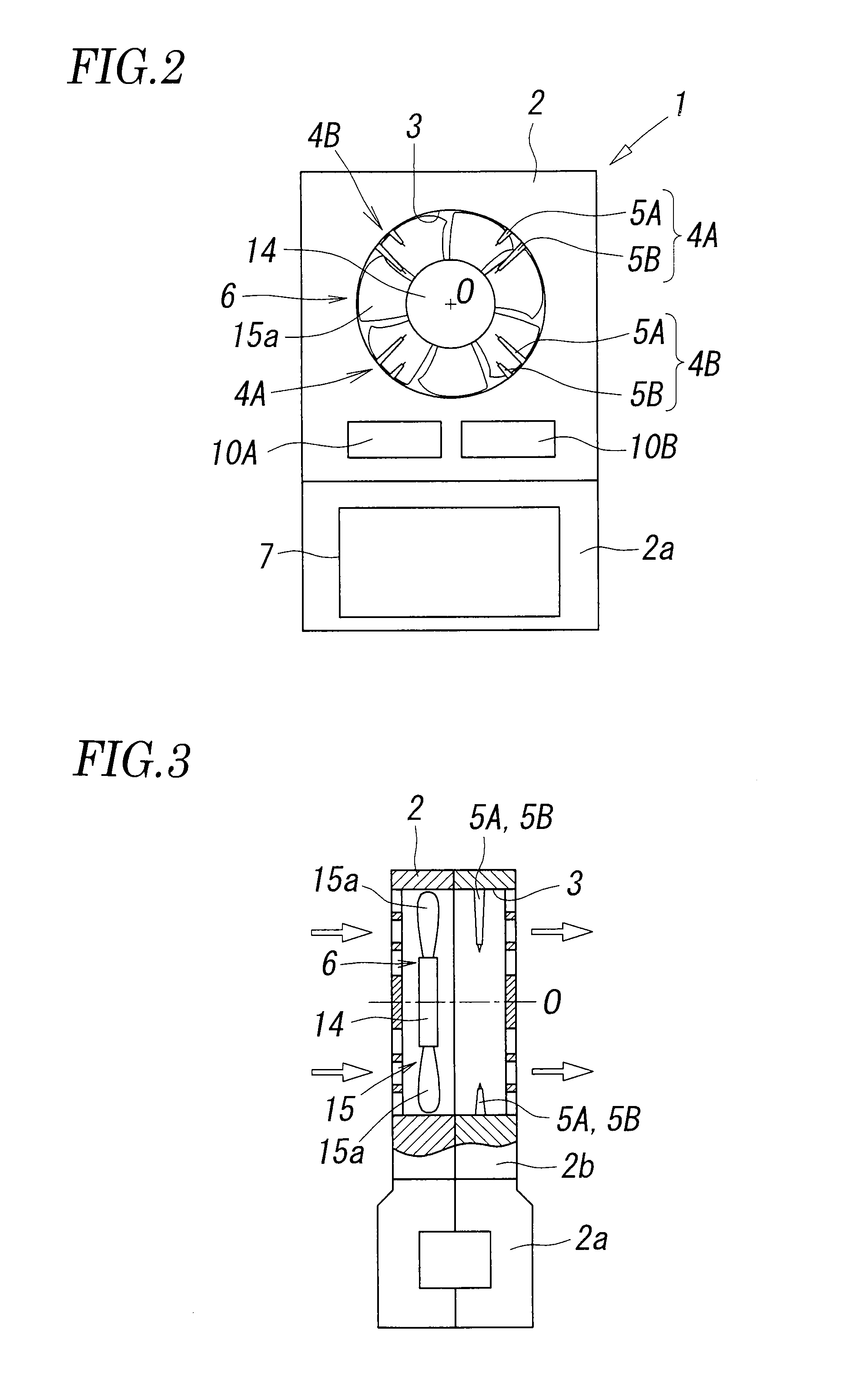
[0015]In the ionizer of the present invention, the distance (tip-center distance) from the tip of a discharge electrode to the center of the air blowing port is different between the two discharge electrodes in the discharge electrode pairs, and thus positive and negative ions are generated at different positions in the radial direction of the air blowing port. Therefore, the flows of the positive and negative ions do not overlap easily even when the ions are carried spirally by a spiral air flow produced by rotation of the fan. As a result, the amount of ions to be neutralized by recombination reduces, and thus the amount of ions that reach a workpiece increases, thereby improving the destaticization efficiency.

Problems solved by technology

As a result, the amount of ions that reach a workpiece may be reduced, causing a problem that a removal efficiency of electricity falls.

Method used


Image

  • Ionizer
  • Ionizer
  • Ionizer

Examples


Embodiment Construction

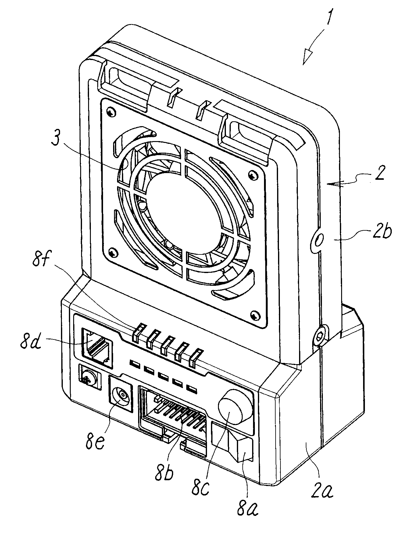
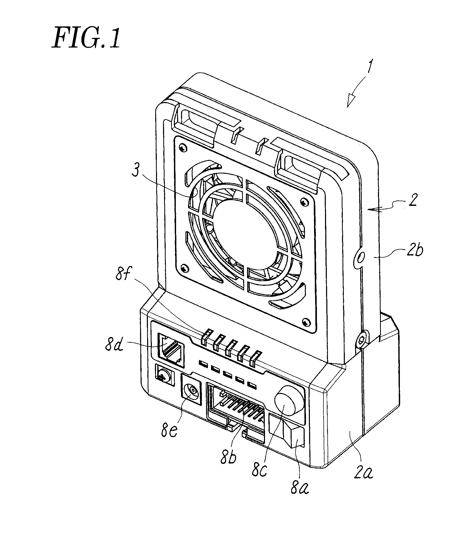
[0026]FIGS. 1 to 3 schematically show a first embodiment of an ionizer in accordance with the present invention. An ionizer 1 has a substantially rectangular case 2 formed of a synthetic resin. The case 2 has a base part 2a that is wider in the front-and-back direction than an ion generation part 2b that extends upward from the base part 2a. However, the base part 2a and the ion generation part 2b may have the same widths in the front-and-back direction. In addition, the base part 2a and the ion generation part 2b may be formed integrally with each other, or may be formed separately from each other and coupled to each other in a detachable manner.

[0027]The base part 2a houses a control device 7 for controlling the operation of the overall ionizer. The front surface of the base part 2a is provided with a power switch 8a, a connector 8b for connecting a wire to an external power source or an external instrument, a rotary switch 8c for air volume control, a modular connector 8d for con...


PUM


Abstract

An ionizer includes a fan for blowing air, the fan being provided in an air blowing port which opens in a case, and a plurality of discharge electrodes for generating positive and negative ions by corona discharge, the discharge electrodes being provided in the case at positions facing the air blowing port. The ionizer also includes a plurality of discharge electrode pairs each constituted by two discharge electrodes for generating ions of different polarities. When a tip-center distance denotes a distance from the electrode tip to the center of the air blowing port, the tip-center distances of the two discharge electrodes in the discharge electrode pairs are different from each other.

Description

TECHNICAL FIELD[0001]The present invention relates to an ionizer for removing electric charge from (netralize) a workpiece electrified with positive or negative charge, and more specifically to a fan-type ionizer including discharge electrodes for generating positive and negative ions and a fan for producing an air flow carrying the ions.BACKGROUND ART[0002]In treatment processes for various workpieces such as semiconductor wafers and liquid crystal glass, ionizers are used to neutralize (destaticize) positive or negative charge on an electrostatically charged workpiece. Some ionizers utilize corona discharge while others utilize soft X-rays. The ionizers utilizing corona discharge are roughly classified into a direct-current ionizer and an alternating-current ionizer. In general, the direct-current type ionizer has needle-like positive discharge electrodes and negative discharge electrodes. When positive and negative high-voltages are applied to the discharge electrodes, corona dis...

Claims


Application Information

Patent Timeline
Patent Type & Authority Applications(United States)
IPC IPC(8): H05F3/00
CPCH01T23/00H01L21/265
Inventor ORIHARA, MASAYUKITOSHIDA, TAKAYUKITADANO, AKIRA
Owner SMC CORP
Learn More