Efficient fiber ball post-processing device

A processing device and fiber ball technology, which is applied in the field of polyester staple fibers, can solve the problems of inability to ensure the uniformity of short fibers, reduce the probability of antistatic properties, and fall on the transmission line, so as to improve the antistatic efficiency, improve product quality, Stabilize the effect of liquid dip work

Inactive Publication Date: 2021-05-04
郑欢欢
View PDF0 Cites 0 Cited by
  • Summary
  • Abstract
  • Description
  • Claims
  • Application Information

AI Technical Summary

Problems solved by technology

[0005] The purpose of the present invention is to address the deficiencies of the prior art, by setting the slag rejection assembly to cooperate with the output assembly, so that when the slag rejection assembly is outputting, the slag rejection assembly completes the centrifugal rotation of the fiber clusters that have been dipped in electrostatic liquid, and then completes The waste residue on the fiber cluster is thrown off to avoid the waste residue falling on the transmission line during the output process. It needs to be manually cleaned regularly to reduce the probability that the fiber cluster will affect the antistatic property of the product during transmission. At the same time, during the centrifugal rejection process, the The excess electrostatic liquid is thrown into the electrostatic liquid storage box for collection, and the fiber clusters on the retrieving assembly are pulled down by two sets of limit rails b during the rotation until the fiber clusters fall off and fall onto the conveyor belt to realize automatic output. This solves the technical problem that the waste fibers that stay on the production line after output cause interference to the fibers that have been destaticized due to the inability to ensure that the short fibers are uniformly and fully sprayed with antistatic agents

Method used


Image

  • Efficient fiber ball post-processing device
  • Efficient fiber ball post-processing device
  • Efficient fiber ball post-processing device

Examples


Embodiment 1

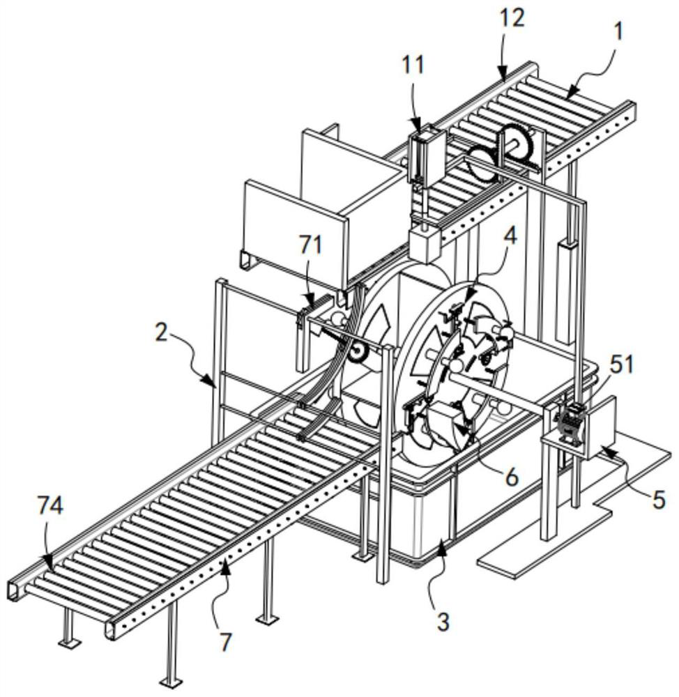
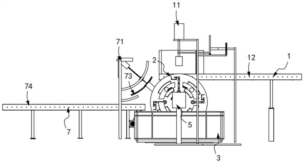
[0078] Such as figure 1 with figure 2 As shown, a high-efficiency fiber ball post-processing device includes an input device 1, an electrostatic treatment device 2 arranged at the output end of the input device 1, and an electrostatic liquid storage box 3 arranged below the electrostatic treatment device 2;

[0079] The electrostatic treatment device 2 includes a station switching mechanism 4, a driving mechanism 5 for driving the station switching mechanism 4 to rotate in a circle, a draining mechanism 6 for draining the destaticized fiber cluster 10, and a For the output mechanism 7 that will complete the output of the fiber cluster after the static electricity removal, the station switching mechanism 4 is sequentially provided with a material receiving station 201, a pretreatment and breaking up station 202, a static electricity removal station 203, and a draining station along its transmission direction. Drying station 204 and slag removal station 205, the draining mecha...

Embodiment 2

[0129] Such as Figure 23 to Figure 24 As shown, the components that are the same as or corresponding to those in the first embodiment are marked with the corresponding reference numerals in the first embodiment. For the sake of simplicity, only the differences from the first embodiment will be described below. The difference between this embodiment two and embodiment one is:

[0130] further, such as Figure 23 to Figure 24As shown, the intermittent discharge mechanism 12 includes a transmission belt 121, a push plate a122 that moves along the width direction of the transmission belt 121 and is fixedly connected with the driving rack a118, and a stopper that is arranged at the output end of the transmission belt 121 Block 123, the pushing plate a122 is set in a multi-section right-angle plate structure.

[0131] In this embodiment, by setting the push-down mechanism 11 to cooperate with the intermittent discharge mechanism 12, the fiber cluster 10 on the intermittent discha...


PUM


Abstract

The invention relates to an efficient fiber ball post-processing device. The efficient fiber ball post-processing device comprises an input device, an electrostatic treatment device and an electrostatic liquid storage box; the electrostatic treatment device comprises a station switching mechanism, a driving mechanism, a draining mechanism and an output mechanism; the station switching mechanism is sequentially provided with a material receiving station, a pretreatment scattering station, an electrostatic eliminating station, a draining station and a slag throwing station in the transmission direction of the station switching mechanism; the draining mechanism is located on the draining station; the output mechanism is located on the slag throwing station; the station switching mechanism is provided with a plurality of sets of positioning assemblies at equal intervals in the circumferential direction, and any positioning assembly is matched with a control assembly in the circumferential rotation process to achieve positioning and scattering work on fiber balls; and the input device comprises a push-down mechanism and a discontinuous discharging mechanism; The efficient fiber ball post-processing device solves the technical problem that waste fibers staying on a production line after output cause interference on static-removed fibers due to the fact that it cannot be guaranteed that short fibers are evenly and fully sprayed with an antistatic agent.

Description

technical field [0001] The invention relates to the technical field of polyester staple fibers, in particular to a high-efficiency fiber ball post-processing device. Background technique [0002] Polyester staple cotton is prone to static electricity during the production process, and it is necessary to spray antistatic liquid on the staple cotton. In the existing processing flow, a manual hand-held spray gun is used to spray antistatic agent on the output short-fiber cotton. The problem with this processing method is that it will consume a large labor cost, and the manual operation will inevitably lead to the problem of missing antistatic agent or uneven spraying of antistatic agent. Therefore, how to develop a new type of non-woven fabric opening and blending production equipment that can overcome the above problems is a direction that those skilled in the art need to study. [0003] The Chinese utility model patent with the application number CN2017211942284 discloses a...

Claims


Application Information

Patent Timeline
IPC IPC(8): D06B3/02D06B15/00D06B15/10D06B23/20D06B23/04
CPCD06B3/02D06B15/005D06B15/10D06B23/04D06B23/20
Inventor 郑恒郑欢欢
Owner 郑欢欢
Why Eureka
Try Eureka