Variable geometry turbocharger lower vane ring retaining system

a technology of retaining system and turbocharger, which is applied in the direction of machines/engines, stators, liquid fuel engines, etc., can solve the problems of detriment to the components of the turbocharger, aerodynamic inefficiencies, twisting motion, etc., and achieves the effect of minimizing the effect of thermal growth, reducing the potential for vanes to stick, and maintaining efficiency

Active Publication Date: 2010-01-14
BORGWARNER INC
View PDF8 Cites 28 Cited by
  • Summary
  • Abstract
  • Description
  • Claims
  • Application Information

AI Technical Summary

Benefits of technology

[0025]As illustrated in the exemplary embodiments, the vane ring assembly effectively decouples the assembly from the turbine housing and eliminates the potential for vanes to stick due to relative movement through thermal growth, as is experienced when the lower and upper vane support rings are rigidly affixed to the turbine housing via studs, bolts, and the like.
[0026]The exemplary embodiments provide a fastening system and method for connecting the vane ring assembly to the turbine housing that minimizes the effect of thermal growth, or the effects of differential thermal growth, of the housing and / or vane ring assembly while maintaining efficiencies. The exemplary embodiments are cost effective, dependable, and are designed for ease of assembly.
[0027]In accordance with the invention, by using a first set of fasteners to fasten the lower vane ring to the turbine housing, and a second set of fasteners to fasten the lower vane ring to the upper vane ring, the vane ring assembly is effectively decoupled from the turbine housing and the co-planerism of the vane rings is easier to maintain.

Problems solved by technology

Such conditions have a detrimental effect on the components of the turbocharger.
The design selections, required to satisfy these conditions, often lead to larger than preferred clearances, which, in turn, cause aerodynamic inefficiencies.
This often results in a twisting motion, dependant upon the constraints of the casting geometry.
This relatively simple thermal expansion, combined with the results of the geometric and thermal flux influences, results in complex deformation of the turbine housing across the temperature range.
This displacement of the fastener causes distortion in the vane rings, which then causes the vanes and moving components to jam.
If the clearances between components are loosened in order to reduce sticking of the vanes, the added buffer clearances cause a loss of aerodynamic efficiency, which is unacceptable.
The displacement of the fasteners also generates high stress in the fastener, which results often in failure of the fastener.
Unusual wear patterns, due to distortion in the vane ring, also generate unwanted clearances, which further reduce the aerodynamic efficiency.
Tapped holes are a reasonably efficient manufacturing method but are simply not effective when it comes to dimensional accuracy or repeatability.
While it is normal practice to generate acceptable accuracy and repeatability with drilled or reamed holes, the threading activity is fraught with problems.
Due to the integral connection of the housing (1) with the vane table (6), the Fukaya turbocharger suffers from the drawbacks of having to allow clearances to account for thermal growth.
Such gaps reduce the performance of the turbocharger.
Such materials can be costly and difficult to work with.
The Arnold device also suffers from the drawback of radial thermal expansion of the turbine housing imparting undue stress and / or movable components “sticking” due to the use of the vane post connection in the housing.

Method used


Image

  • Variable geometry turbocharger lower vane ring retaining system
  • Variable geometry turbocharger lower vane ring retaining system
  • Variable geometry turbocharger lower vane ring retaining system

Examples


Embodiment Construction

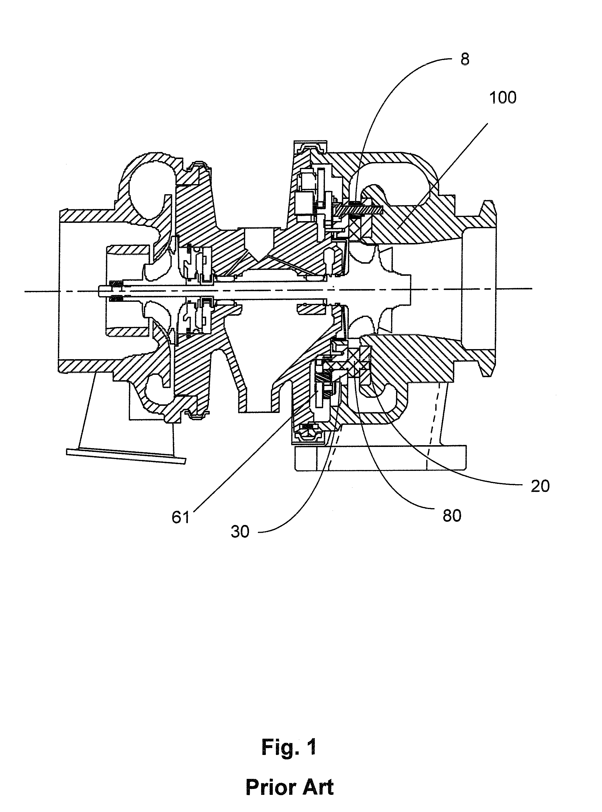
[0049]In the prior art the vanes rings are firmly attached to the turbine housing, which is subjected to a non-homogeneous thermal profile. This means that uneven thermal expansion and deformation in the turbine housing is mechanically imparted to the vane ring assembly (vane rings, mounting hardware and vanes) which causes rubbing between the moving vanes and the static vane rings ultimately causing sticking of the vanes. The inventors realized that by decoupling the vane ring assembly from being rigidly mounted to the turbine housing would remediate the sticking problem.

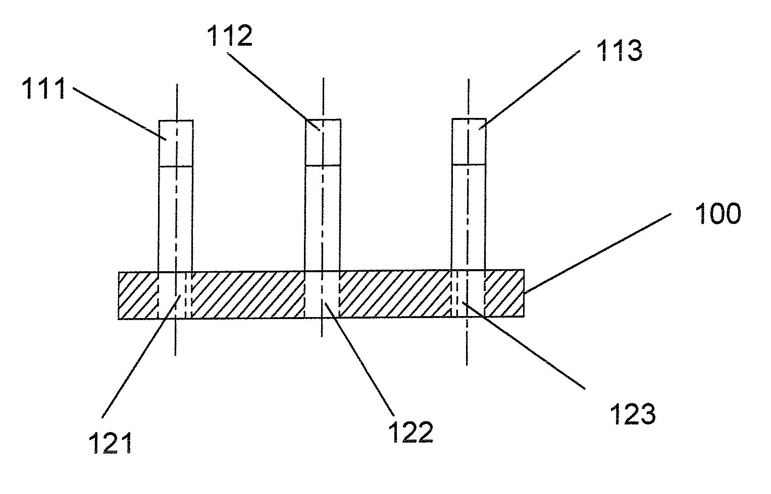
[0050]In accordance with the present invention, as depicted in FIGS. 14 and 15, a first set of fasteners is used to fasten the lower vane ring to the turbine housing, and a second set of fasteners is used to fasten the lower vane ring to the upper vane ring. By not having the upper and lower vane rings fastened to the turbine housing by the same set of fasteners, the vane ring assembly is effectively decoupled from...


PUM


Abstract

A vane ring assembly which includes a lower vane ring (22), an upper vane ring (30), one or more guide vanes (80) positioned at least partially between the vane rings, and a plurality of spacers (42, or 50) positioned between the lower and upper vane rings for maintaining a distance between the lower and upper vane rings. By using a first set of fasteners (190) to fasten the lower vane ring to the turbine housing, and a second set of fasteners (191) to fasten the lower vane ring to the upper vane ring, the vane ring assembly is effectively decoupled from the turbine housing with regard to differential thermal expansion, and the co-planerism of the vane rings is easier to maintain.

Description

FIELD OF THE INVENTION[0001]This invention is directed to a turbocharging system for an internal combustion engine and more particularly to a design of a VTG system, isolating the upper vane ring from the turbine housing, thus allowing reduced stress from differential thermal expansion.BACKGROUND OF THE INVENTION[0002]Turbochargers are a type of forced induction system. They deliver compressed air to the engine intake, allowing more fuel to be combusted, thus boosting the engine's horsepower without significantly increasing engine weight. This can allow for the use of a smaller turbocharged engine, replacing a normally aspirated engine of a larger physical size, thus reducing the mass and aerodynamic frontal area of the vehicle. Turbochargers use the exhaust flow from the engine to drive a turbine, which is mechanically connected to a compressor. At startup, the turbocharger may be at temperatures well below 0° C. Since the turbine spins at extremely high speed, in the range of 150,...

Claims


Application Information

Patent Timeline
Patent Type & Authority Applications(United States)
IPC IPC(8): F01D1/02
CPCF01D9/041F01D17/165F05D2220/40F05D2260/941F05D2260/94
Inventor SCHOLZ, GEORGHALL, RICHARDHEDDY, III, GEORGE E.
Owner BORGWARNER INC
Why Eureka
Try Eureka