Chucking device for use in machining exhaust gas purifying system

Inactive Publication Date: 2010-01-21
YUTAKA GIKEN CO LTD
View PDF17 Cites 5 Cited by
  • Summary
  • Abstract
  • Description
  • Claims
  • Application Information

AI Technical Summary

Benefits of technology

[0020]When the outside diameter of the cylinder is larger than the reference outside diameter, the two ends of the contact surface will be the only parts in contact with the cylinder when chucking commences. When the chamfers at either end are excluded the contact surface is reduced. A smaller contact surface corresponds to lesser effect on the catalyst. However, the pressing pieces will be subjected to a reactive force from the cylinder, and since they are larger than the contact surfaces, the rigidity of the pressing pieces can be adequately increased. Specifically, it is possible to lessen the effect on the catalyst while maintaining the rigidity of the pressing pieces.
[0023]When the chamfers at either end are excluded the contact surface is reduced. A smaller contact surface corresponds to lesser effect on the catalyst. However, the pressing pieces will be subjected to a reactive force from the cylinder, and since they are larger than the contact surfaces, the rigidity of the pressing pieces can be adequately increased. Specifically, it is possible to lessen the effect on the catalyst while maintaining the rigidity of the pressing pieces. In addition, the effect of the pressing force is also applied to the arcuate surfaces during diameter-reduction; therefore, the final shape of the completed product is improved.

Problems solved by technology

This method requires the diameter to be reduced to the proper degree since the catalyst will be inadequately secured if the diameter is insufficiently reduced, while the catalyst will be damaged it the diameter is excessively reduced.
The fact that the diameter can only be reduced to a certain degree means that irregularities may arise in the outside diameter of the cylinder.
The effect on the catalyst increases according to the extent of local deformation, and the catalyst may suffer damage.
When the number of segments increases, the size of the clamp decreases, and the rigidity decreases, leading to concerns that the rigidity will be insufficient.

Method used


Image

  • Chucking device for use in machining exhaust gas purifying system
  • Chucking device for use in machining exhaust gas purifying system
  • Chucking device for use in machining exhaust gas purifying system

Examples


Embodiment Construction

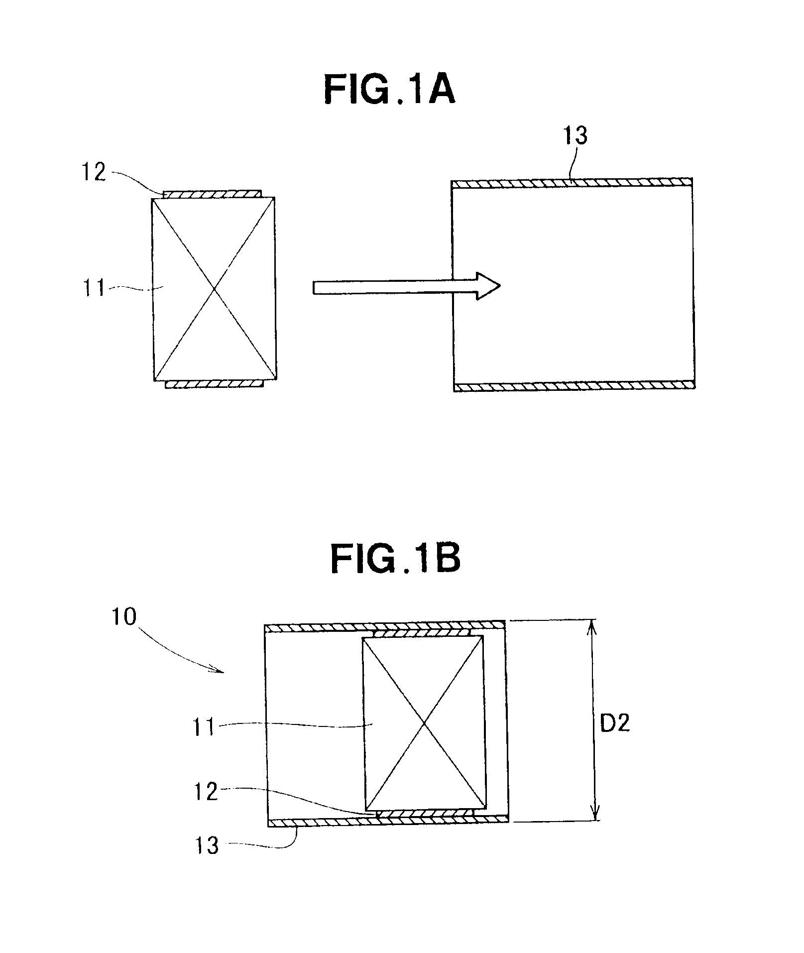
[0037]As shown in FIG. 1A, a pillar-shaped catalyst 11 is wrapped in a mat 12 and inserted into a metal cylinder 13. It is thereby possible to obtain a semi-finished version 10 of the exhaust pipe shown in FIG. 1B. It is also possible to provide a diameter-reducing step between the events depicted in FIG. 1A and FIG. 1B, and subject the metal cylinder 13 to a diameter-reducing process. The article obtained after the diameter has been reduced will be the semi-finished product 10. An outside diameter of the semi-finished product 10 is indicated by D2.

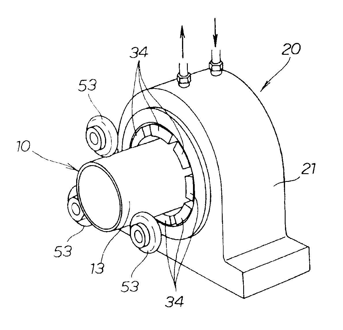
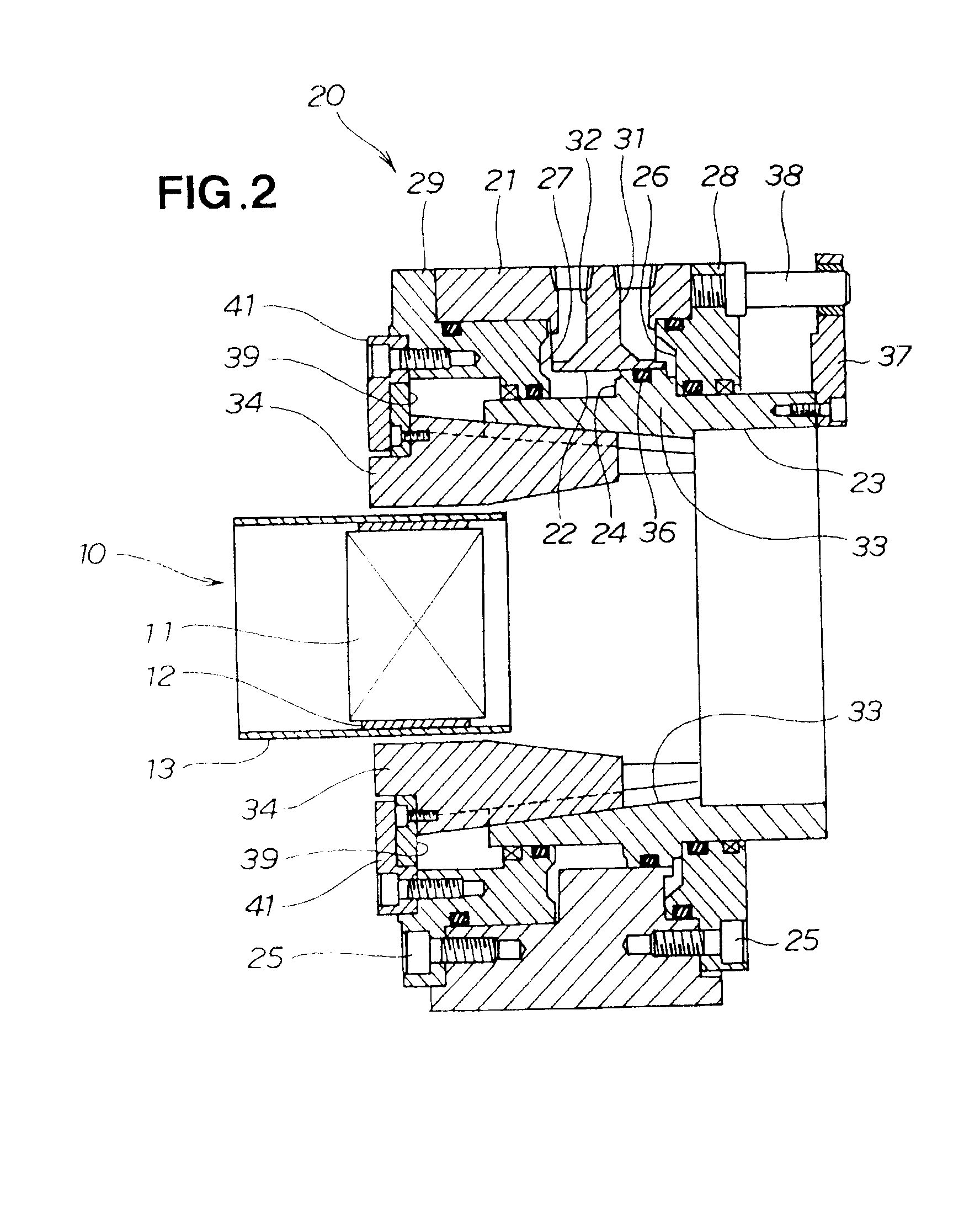
[0038]Reference is now made to FIG. 2 showing a chucking device 20 for use in machining an exhaust-gas purifying system. The chucking device 20, which is used for gripping the semi-finished product 10, comprises a case 21; a sliding tube 23 inserted into a large hole 22 opening laterally with respect to the case 21, the sliding tube 23 being capable of moving to the left and right with respect to the drawing; a piston 24 integrally formed...


PUM

PropertyMeasurementUnit
Pressureaaaaaaaaaa
Radiusaaaaaaaaaa

Abstract

A chucking device for use when an outer peripheral end part of a semi-finished product having a pillar-shaped catalyst wrapped in a mat and housed in a cylinder is spin-processed using a plurality of spinning rollers. An outer peripheral surface of the semi-finished product is chucked using a plurality of pressing pieces. Each of the pressing pieces has a contact surface for touching the cylinder of the semi-finished product, and a pair of chamfers extending radially outward from either end of the contact surface.

Description

FILED OF THE INVENTION[0001]The present invention relates to a technique for machining a system for purifying exhaust gas, wherein spin-processing is performed on an end of a cylinder.BACKGROUND OF THE INVENTION[0002]A variety of systems for purifying exhaust gas have been commercialized for use as effective means for complying with emissions regulations. Among these, systems constructed having a catalyst encased in a cylinder so as to be disposed inside the exhaust pipe of a vehicle are in widespread use as systems for purifying vehicle exhaust gas. Fulfilling its purifying function causes the catalyst to become larger than the diameter of the exhaust pipe. Accordingly, it is necessary to reduce the diameter of an end part of the cylinder encasing the catalyst to match the front and rear diameters of the exhaust pipe.[0003]The process for reducing the diameter is performed using spin-processing as disclosed in, e.g., JP 2002-239657 A. The spin-processing disclosed in JP 2002-239657...

Claims


Application Information

Patent Timeline
IPC IPC(8): B23B31/40
CPCB23B31/16241B23B31/16254B23B2215/64Y10T279/1291Y10T279/17743Y10T279/1021Y10T279/1986
Inventor YAMAZAKI, AKIRAKAGEYAMA, YASUSHIKAWAMATA, AKIHIRONAKAMURA, TOMOYA
Owner YUTAKA GIKEN CO LTD
Why Eureka
Try Eureka