Structure for connection between integrated panel and fluid device

a technology of fluid device and integrated panel, which is applied in the direction of hose connection, pipe-joint, engine seal, etc., can solve the problems of reducing the workability of connection and coupling, the bolt fastening force is reduced with time, etc., and achieves excellent sealing properties, increased circulating flow amount, and reduced apparatus occupation area

Inactive Publication Date: 2010-01-21
NIPPON PILLAR PACKING CO LTD
View PDF7 Cites 6 Cited by
  • Summary
  • Abstract
  • Description
  • Claims
  • Application Information

AI Technical Summary

Benefits of technology

[0040]According to the invention of claim 1, means is provided for forming two or more fluid passages as concentric multiplex pipes, thereby compactifying a connecting structure portion as compared with a structure in which plural fluid passages are independently arranged. The annular projections formed respectively on the first and second fluid supply / discharge port portions, and the annular grooves formed respectively in the one and other end faces of the gaskets are fitted to each other to form fitting sealing portions. Therefore, an excellent sealing property of blocking liquid leakage from between the first and second fluid supply / discharge port portions can be obtained. When this connecting structure is used in a piping system for a cleaning apparatus in a semiconductor device producing facility, for example, the occupation area of the apparatus can be reduced while ensuring an excellent sealing property, and hence the structure is advantageous from the viewpoint of cost. Furthermore, a large fluid path can be ensured, and hence the circulating flow amount can be increased, and the purities of chemicals can be made higher, thereby attaining an effect that the invention can contribute to improvement of the yield.
[0041]The holding means can hold the joined state where the fluid supply / discharge port portions are attracted to each other via the gasket. Therefore, it is possible to provide a highly reliable connecting structure for an integration panel and a fluid device by which the state where liquid leakage does not occur in the integration panel and the fluid device and the excellent sealing property can be ensured can be held for a long term.
[0042]In a fitting structure in which a convex is inserted into a concave, it is generally known that, even when they are made of the same material, the convex-side member is hardly changed (compressively deformed), and the concaveside member tends to be expandingly deformed. In claim 1, therefore, the annular projections which are convex are formed on the fluid device, and the annular grooves which are concave are formed in the gaskets. Accordingly, a component which may be deformed because of occurrence of creep or aging is on the side of the gaskets which are smaller than the fluid device, and components of the fluid device are hardly deformed. Consequently, there is an effect that the advantage that an excellent sealing property can be held for a long term by replacing the gaskets can be economically realized. Moreover, in the intermediate gasket where the fluid passages are formed outside and inside of the gasket, not only the inner peripheral portion of the gasket, but also the outer peripheral portion functions also as a wall of a fluid path. Therefore, inner and outer fluid passages which are adjacent to each other are separated only by the thickness of the intermediate gasket, and plural fluid passages can be placed closely in a radial direction as far as possible. Accordingly, there is an advantage that the connecting structure for an integration panel and a fluid device can be further compactified. As a result, a connecting structure for an integration panel and a fluid device in which plural fluid passages are concentrically arranged and connected can be realized. Therefore, the invention can contribute to promotion of integration of fluid devices which can be advantageously modularized or compactified, and provide a connecting structure for an integration panel and a fluid device in which an excellent sealing property can be held for a long term, the reliability is high, and further compactification is enabled.
[0043]According to the invention of claim 2, there are the following effects. As described above, in concavo-convex fitting, the concave side tends to be expandingly deformed. It means that, in the invention, the inner and outer peripheral wall end portions which are formed in the gasket in order to form the annular grooves are expandingly deformed. Since the annular press portions which suppress or block expanding deformations of the peripheral wall end portions are disposed in the first and second fluid supply / discharge port portions, expanding deformations of the peripheral wall end portions are eliminated or reduced, and the annular projections and the annular grooves can be fitted together by a strong press contact force. The excellent sealing function due to the fitting between them can be exerted as desired. Moreover, the existence of the annular press portions can compensate insufficient rigidity of the peripheral wall end portions. Therefore, the thicknesses of the peripheral wall end portions of the gasket can be reduced as compared with the case where the portions are not disposed. Consequently, there are advantages that the width of the gasket can be reduced, whereby the whole diameter of plural fluid passages which are concentrically arranged can be compactified, or namely the connecting structure for an integration panel and a fluid device can be further compactified.
[0044]According to the invention of claim 3, in the joined state, the sealing portions due to press contacts between the annular projections of the first and second fluid supply / discharge port portions, and the annular grooves of the one and other end faces of the gaskets are formed. Therefore, it is possible to configure a connecting structure for an integration panel and a fluid device in which the fitting sealing portions having an excellent sealing property are configured, and which exhibits an excellent sealing performance.
[0045]According to the invention of claim 4, there is the configuration where, in the joined state, the tapered peripheral faces of the first and second fluid supply / discharge port portions, and the tapered peripheral face of the gasket are pressingly contacted with each other in the inner and outer diameter sides of the fitting portions between the annular projections of the first and second fluid supply / discharge port portions and the annular grooves of the one or other end faces of the gaskets. Because of the butting contacts of the tapered peripheral faces, it is possible to attain the both effects of compactification of the connecting structure portion (claim 2) and improvement of the sealing property (claim 3). Since the structure in which the tapered peripheral faces butt against each other is employed, moreover, the press contact force is more increased as the fluid devices are further strongly pressed against the gasket, thereby producing an advantage that the effects of compactification and improvement of the sealing property can be further enhanced. Accordingly, it is possible to provide a connecting structure where liquid stagnation does not occur between the tapered peripheral faces.

Problems solved by technology

However, it is inevitable that the fastening force of the bolts is reduced with time.
The case is disadvantageous also in the workability of connection and coupling.

Method used


Image

  • Structure for connection between integrated panel and fluid device
  • Structure for connection between integrated panel and fluid device
  • Structure for connection between integrated panel and fluid device

Examples


embodiment 1

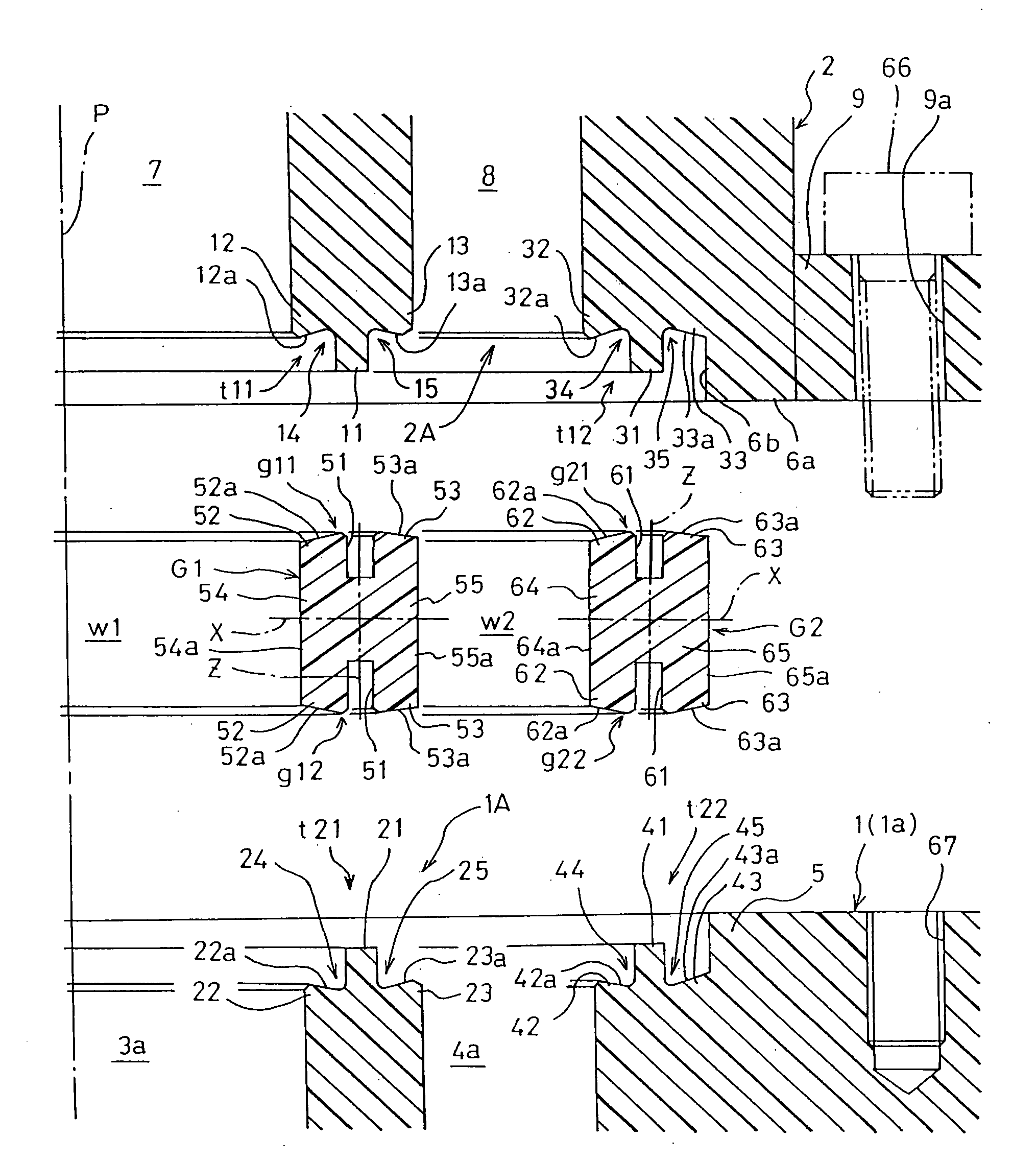
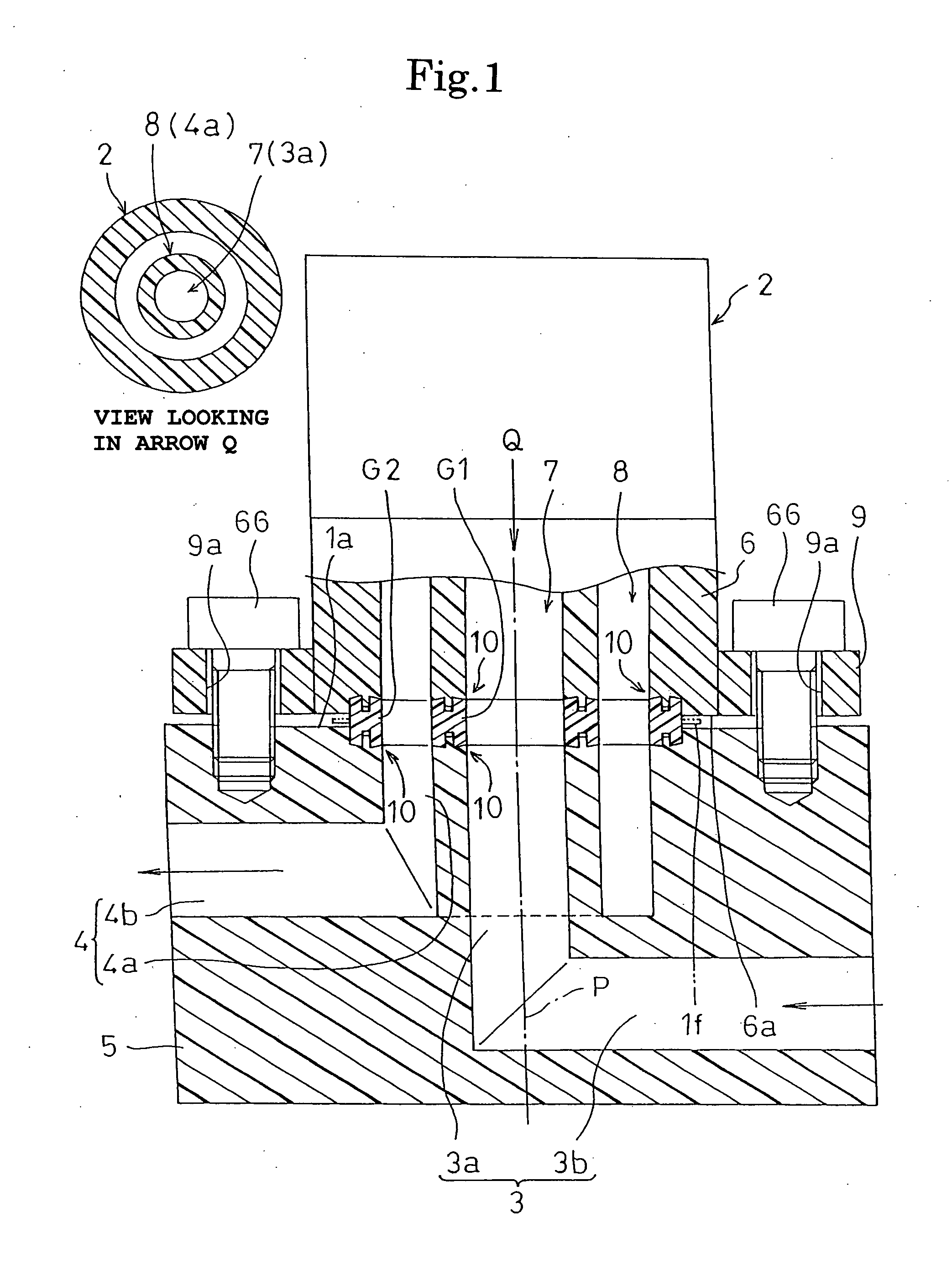
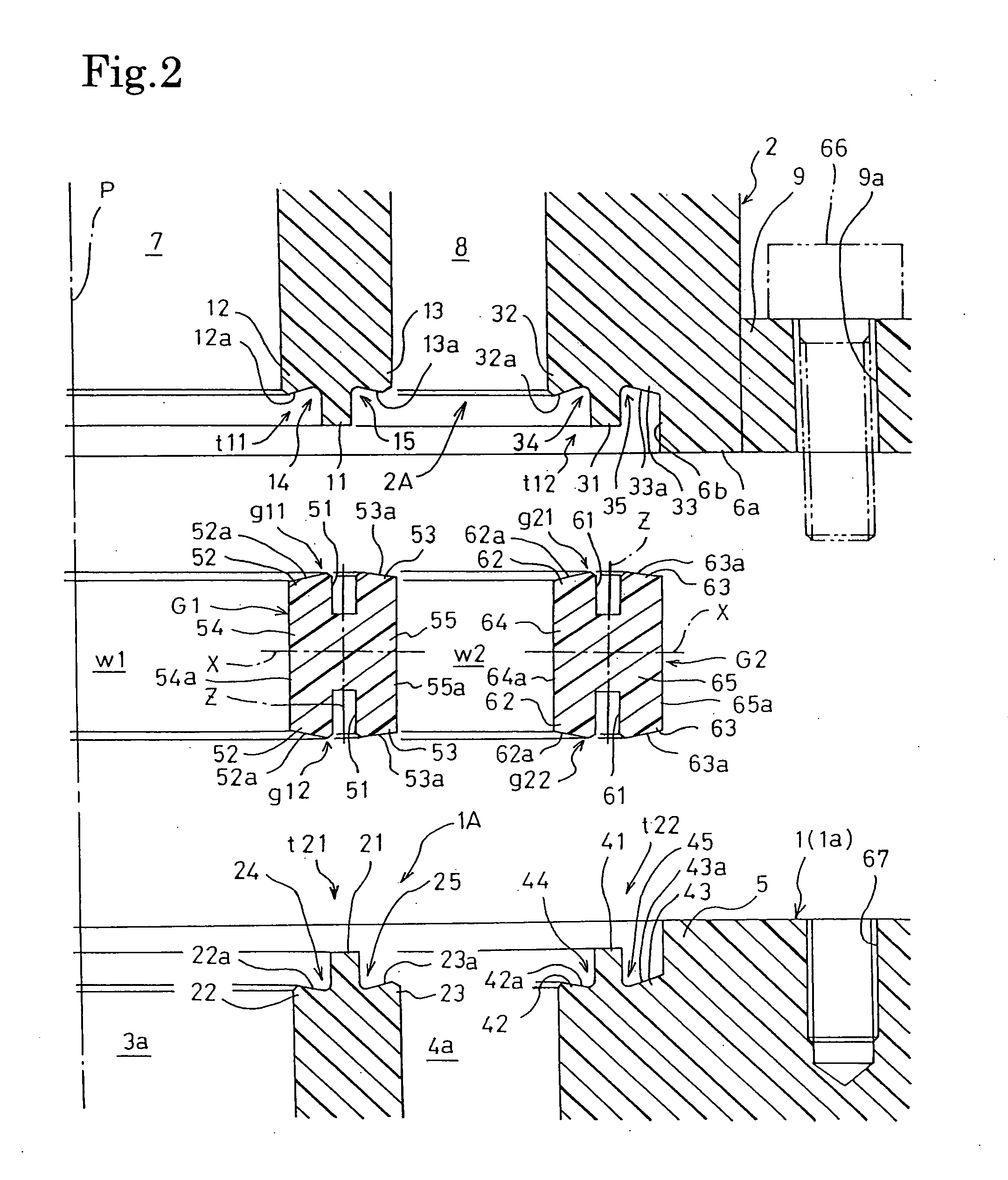
[0122]FIGS. 1 and 2 show a connecting structure for an integration panel and a fluid device according to Embodiment 1. The connecting structure for an integration panel and a fluid device is a concentric double flow path structure that extends over both an integration panel 1 in which plural pipe-like fluid passages 3, 4 are formed, and a valve (such as an on-off valve or a stop valve) 2 which is mounted on the upper face 1a of the panel via inner and outer ring-like gaskets G1, G2 numbering two in total, and that shares the vertical axis P.

[0123]In the integration panel 1, as shown in FIGS. 1 and 2, the pipe-like supply-side fluid passage 3 consisting of: a vertical passage 3a which is vertically formed, and which is opened in the panel upper face 1a; and a lateral passage 3b which laterally extends, and the discharge-side fluid passage 4 consisting of: an annular vertical ring passage 4a which is formed on an outer diameter-side of the vertical passage 3a, and which is opened in t...

embodiment 2

[0144]As shown in FIG. 4, a connecting structure for an integration panel and a fluid device according to Embodiment 2 is used for communicatingly connecting the integration panel 1 to a pump (such as a bellows pump for a circulation line of a cleaning apparatus) 2 which is an example of a fluid device, via a flanged pipe 71. The configuration of the connecting structure itself in which the inner and outer gaskets G1, G2 are interposed is identical with that of the connecting structure described in Embodiment 1. Therefore, only principal components are denoted by reference numerals, and the detailed description of the configuration is omitted.

[0145]The integration panel 1 is basically identical in structure except that the direction of the discharge-side fluid passage 4 is opposite to that in the case of the integration panel 1 of Embodiment 1. In the configuration of Embodiment 1, however, the connecting structure for the integration panel and the fluid device is configured on the ...

embodiment 3

[0148]FIGS. 5 and 6 show a connecting structure for an integration panel and a fluid device according to Embodiment 3. The connecting structure is different only in the holding means I from that of Embodiment 1. The holding means I of a first other structure will be described. In FIGS. 5 and 6, portions corresponding to those of Embodiment 1 shown in FIGS. 1 to 3 are denoted by corresponding reference numerals. As shown in FIGS. 5 and 6, the holding means I of the first other structure is configured by: a cylindrical nut 81 having an internal thread portion 81n which is screwable with an external thread portion in formed on an outer peripheral portion of the projection-like first fluid supply / discharge port portion 1A that is formed on the upper face of the integration panel 1, and that is circular in a plan view; and a split ring 82 which has two or three or more split pieces, and which interferes in the direction of the axis P of the annular fluid passage 7 with the outward flange...


PUM


Abstract

A connecting structure for an integration panel and a fluid device which, in order to promote integration of fluid pipes, can be further compactified is provided. In a concentric double flow path type connecting structure, an integration panel 1 and a valve 2 are connected to each other in a sealed state via inner and outer annular gaskets G1, G2 while pipe-like fluid passages 3a, 7 and annular fluid passages 4a, 8 are concentrically arranged. Annular projections 11, 21, 31, 41 are formed on fluid supply / discharge port portions 1A, 2A made of a fluororesin, and annular grooves 51, 61 are formed in the gaskets G1, G2 made of a fluororesin. A joined state where the annular projections and the annular grooves are fitted to each other to form a fitting sealing portion 10 is held by holding means I for attracting together the fluid supply / discharge port portions 1A, 2A and maintaining the attraction. The inner first gasket G1 is configured as a multifunctional intermediate gasket in which the inner peripheral face 54a functions also as the outer walls of the pipe-like fluid passages 3a, 7, and the outer peripheral face 55a functions also as the inner walls of the annular fluid passages 4a, 8.

Description

TECHNICAL FIELD[0001]The present invention relates to a connecting structure for an integration panel and a fluid device, and more particularly to a connecting structure for connecting an integration panel for a fluid which is expected to be largely used, with a fluid device such as a pump, a valve, or an accumulator via a gasket in a sealed state in a piping system or the like for high-purity liquid, ultrapure water, cleaning liquid, or the like that is handled in a production process in various technical fields such as semiconductor production, medical and pharmaceutical production, food processing, and chemical industry.BACKGROUND ART[0002]An example of such a connecting structure is a structure where a valve which is an example of a fluid device is connected and coupled to an integration panel in which a fluid passage is internally formed, by causing a pair of supply / discharge flow paths to communicate with each other. Connecting structures are disclosed in Patent Reference 1 an...

Claims


Application Information

Patent Timeline
Patent Type & Authority Applications(United States)
IPC IPC(8): F16L39/00
CPCF16L39/005F16J15/062F16L39/00F16J15/10F16L19/02
Inventor KATSURA, MASAYOSHI
Owner NIPPON PILLAR PACKING CO LTD
Why Eureka
Try Eureka