


Quick Research
Generate reliable direction feasibility study reports for your R&D in just a few steps.

Technical Q&A
Discover and master advanced knowledge NOW. Basics, ideas, possibilities, all at once.

Find Solutions
As an expert in R&D theories, this can generate solutions to your technical problems instantly.

Evaluate Feasibility
Analyze your overall solution with one click, know your potential R&D risks in advance.

Monitor Landscape
Get weekly tech updates, stay abreast of the latest tech innovations and key insights.
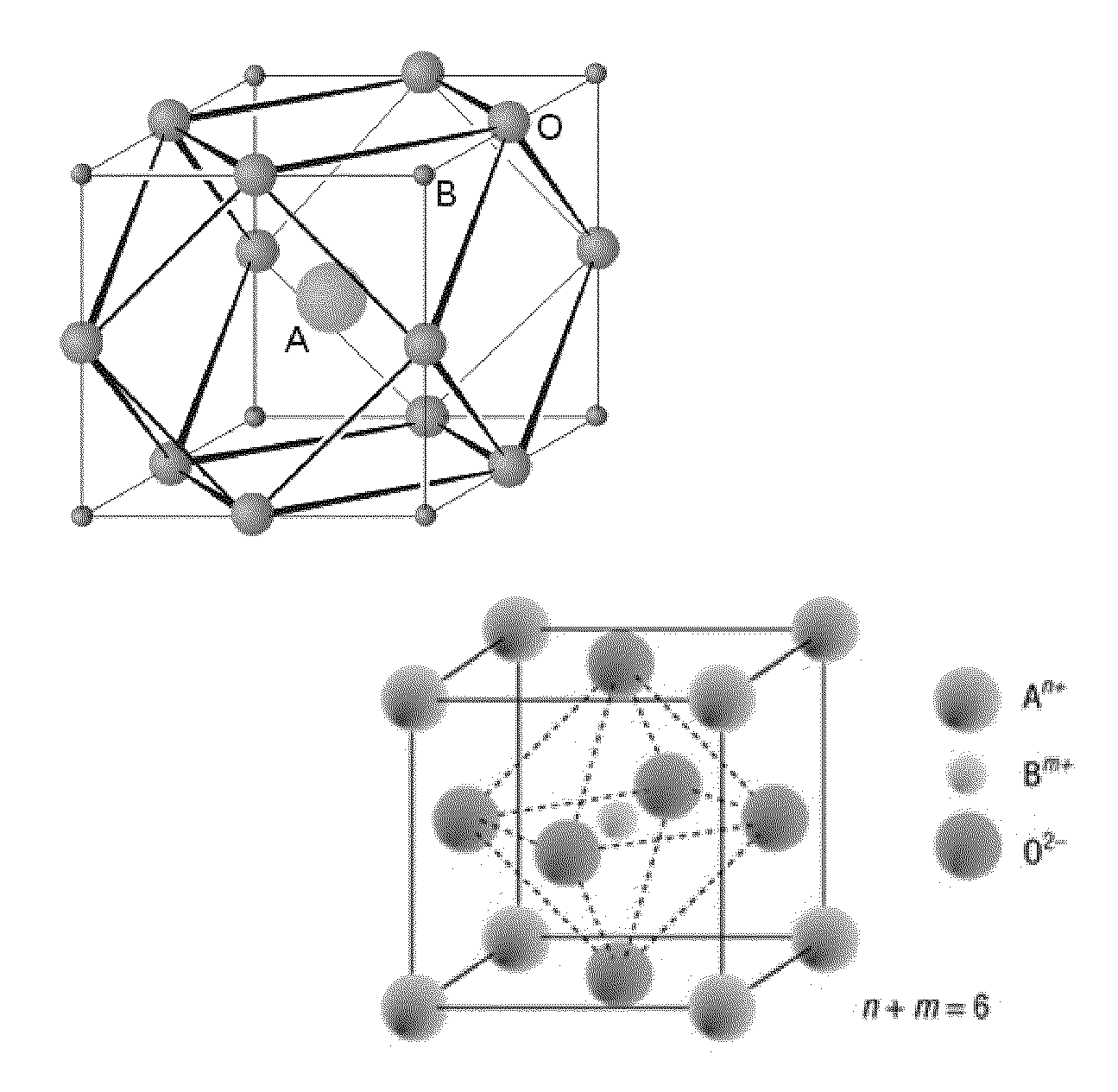
Titanates of Perovskite or Derived Structure and Applications Thereof
- Summary
- Abstract
- Description
- Claims
- Application Information
AI Technical Summary
Benefits of technology
Problems solved by technology
Method used
Image

Examples
example 1
Synthesis of the La0.5Sr0.5Ti0.75Ni0.25O3 Compound (˜4 g) in Pulverulent Form Via a Solid Route
[0098]The La2O3 (1.53782 g), Sr(CO3) (1.39350 g), TiO2 (1.13092 g) and NiO (0.35255 g) precursors were mixed by hand in stoichiometric proportions in an agate mortar in the presence of acetone to facilitate the homogenization. The resulting mixture was calcined at 1200° C. for 12 h in air according to the following heat treatment:
[0099]Then, the compound formed was milled and pressed into the form of a pellet by means of a uniaxial pressing operation. This pellet then underwent a second heat treatment of 24 h at 1350° C. in air.
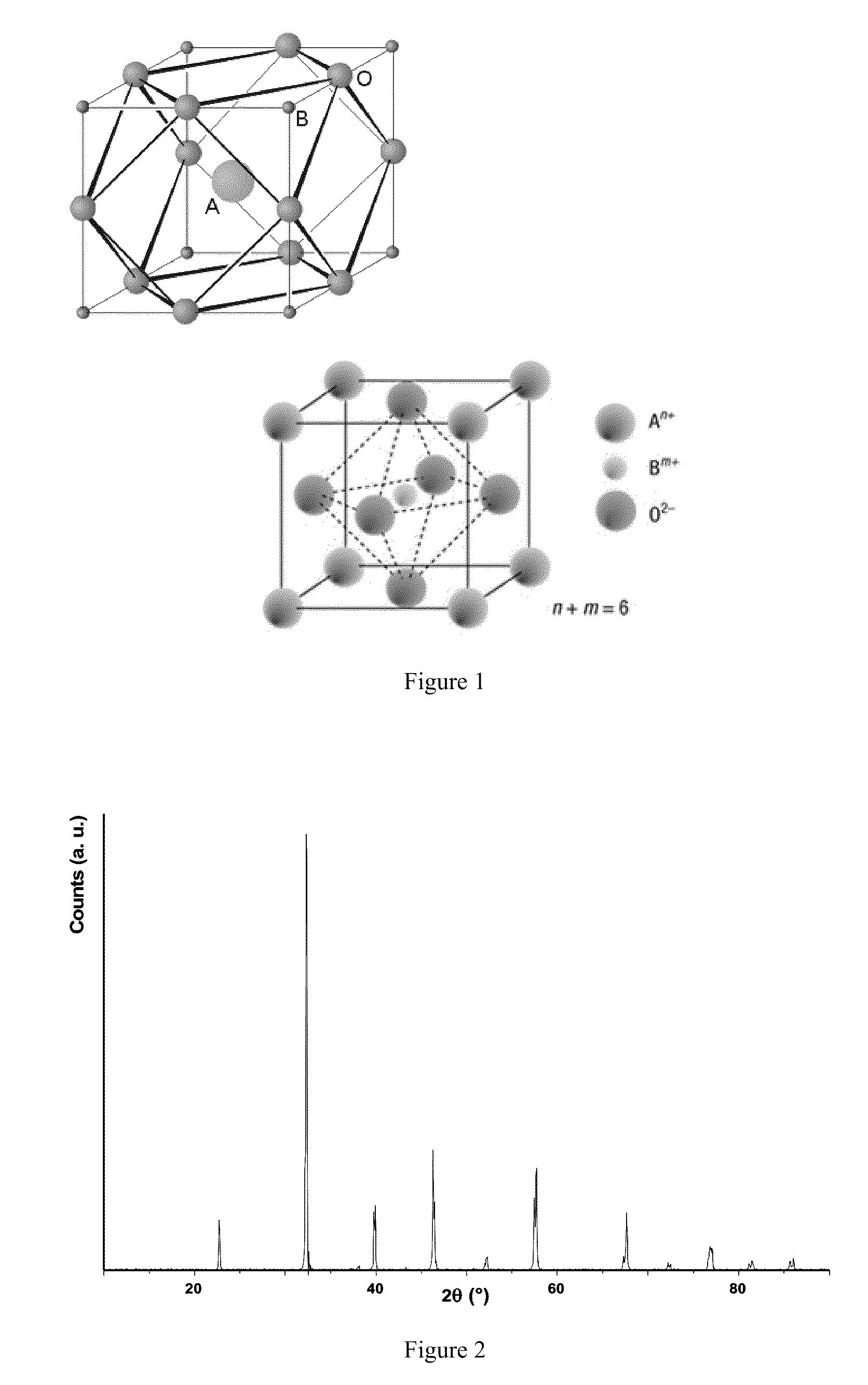
[0100]It was then milled by hand and sieved (20 μm sieve) in order to obtain the powder of La0.5Sr0.5Ti0.75Ni0.25O3. The compound then synthesized was pure as shown by the X-ray powder diffraction diagram from FIG. 2.
example 2
Synthesis of the Ce0.5Sr0.5Ti0.75Ni0.25O3 Compound (˜4 g) in Pulverulent Form Via a Solid Route
[0101]The Ce2(CO3)3 (2.16671 g), Sr(CO3) (1.38984 g), TiO2 (1.12545 g) and NiO (0.35161 g) precursors were mixed by hand in stoichiometric proportions in an agate mortar in the presence of acetone to facilitate the homogenization. The resulting mixture was calcined at 1200° C. for 12 h in a stream of argon (7 ml·h−1) according to the following heat treatment:
[0102]Then, the compound formed was milled and pressed into the form of a pellet by means of a uniaxial pressing operation. This pellet then underwent a second heat treatment of 24 h at 1350° C. in a stream of argon (7 ml·h−1).
[0103]It was then milled by hand and sieved (20 μm sieve) in order to obtain the powder of Ce0.5Sr0.5Ti0.75Ni0.25O3.
example 3
Production, by Screen-Printing, of an Anode Based on La0.5Sr0.5Ti0.75Ni0.25O3 for SOFC
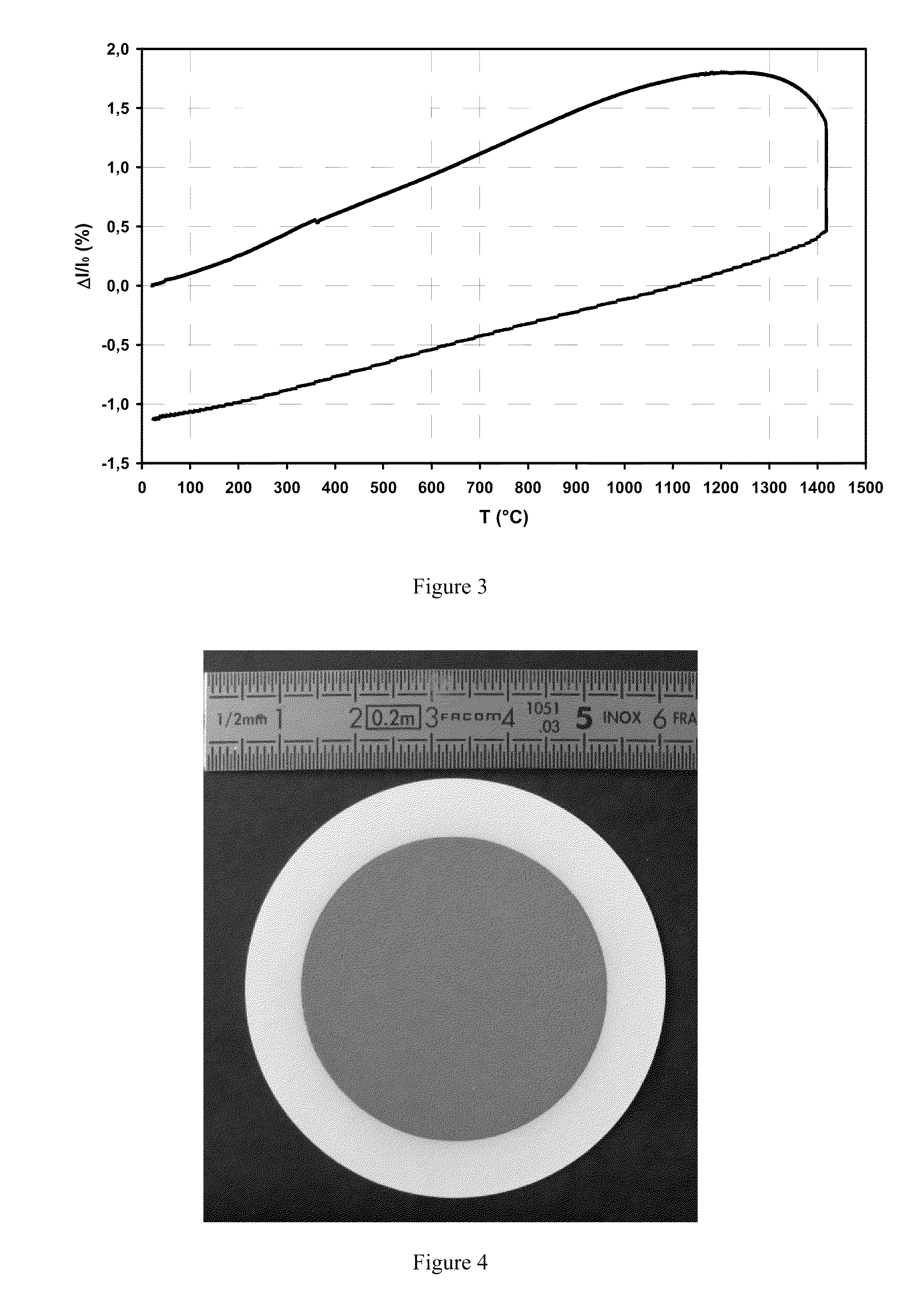
[0104]70 wt % of powder were mixed with 30 wt % of a terpineol / ethyl cellulose mixture (95 / 5 wt %). This preparation was homogenized by hand then by using a three-roll mill (3 successive passes making it possible to obtain a homogenous ink). The ink was then deposited, by screen-printing, on the surface of an (8 mol %) yttria-stabilized zirconia supporting electrolyte. The system formed was then dried for 15 min in an oven at 100° C. In order to give cohesion to the electrode / electrolyte interface and mechanical strength to the deposition, a heat treatment was necessary. The conditions for this treatment were determined via a dilatometry experiment (FIG. 3) carried out in air with vertical geometry on a cylindrical rod of La0.5Sr0.5Ti0.75Ni0.25O3 having a diameter of 10 mm and a thickness of 8.86 mm.
[0105]Thus, 4 h at 1200° C. were sufficient:
[0106]A naturally porous deposition having a thickness o...
PUM
| Property | Measurement | Unit |
|---|---|---|
| Temperature | aaaaa | aaaaa |
| Temperature | aaaaa | aaaaa |
| Time | aaaaa | aaaaa |
Abstract
Description
Claims
Application Information
 - R&D Engineer
- R&D Manager
- IP Professional
- Industry Leading Data Capabilities
- Powerful AI technology
- Patent DNA Extraction
Browse by: Latest US Patents, China's latest patents, Technical Efficacy Thesaurus, Application Domain, Technology Topic, Popular Technical Reports.
© 2024 PatSnap. All rights reserved.Legal|Privacy policy|Modern Slavery Act Transparency Statement|Sitemap|About US| Contact US: help@patsnap.com