

Use of fluid aspiration/dispensing tip as a microcentrifuge tube
a technology of fluid aspiration and dispensing tip, which is applied in the direction of burettes/pipettes, biomass after-treatment, laboratory glassware, etc., can solve the problems of limiting the overall efficiency of these analyzers, affecting the efficiency of patient samples, and unable to remedy the inefficiency of patient sample processing,
- Summary
- Abstract
- Description
- Claims
- Application Information
AI Technical Summary
Benefits of technology
Problems solved by technology
Method used
Image

Examples
first embodiment
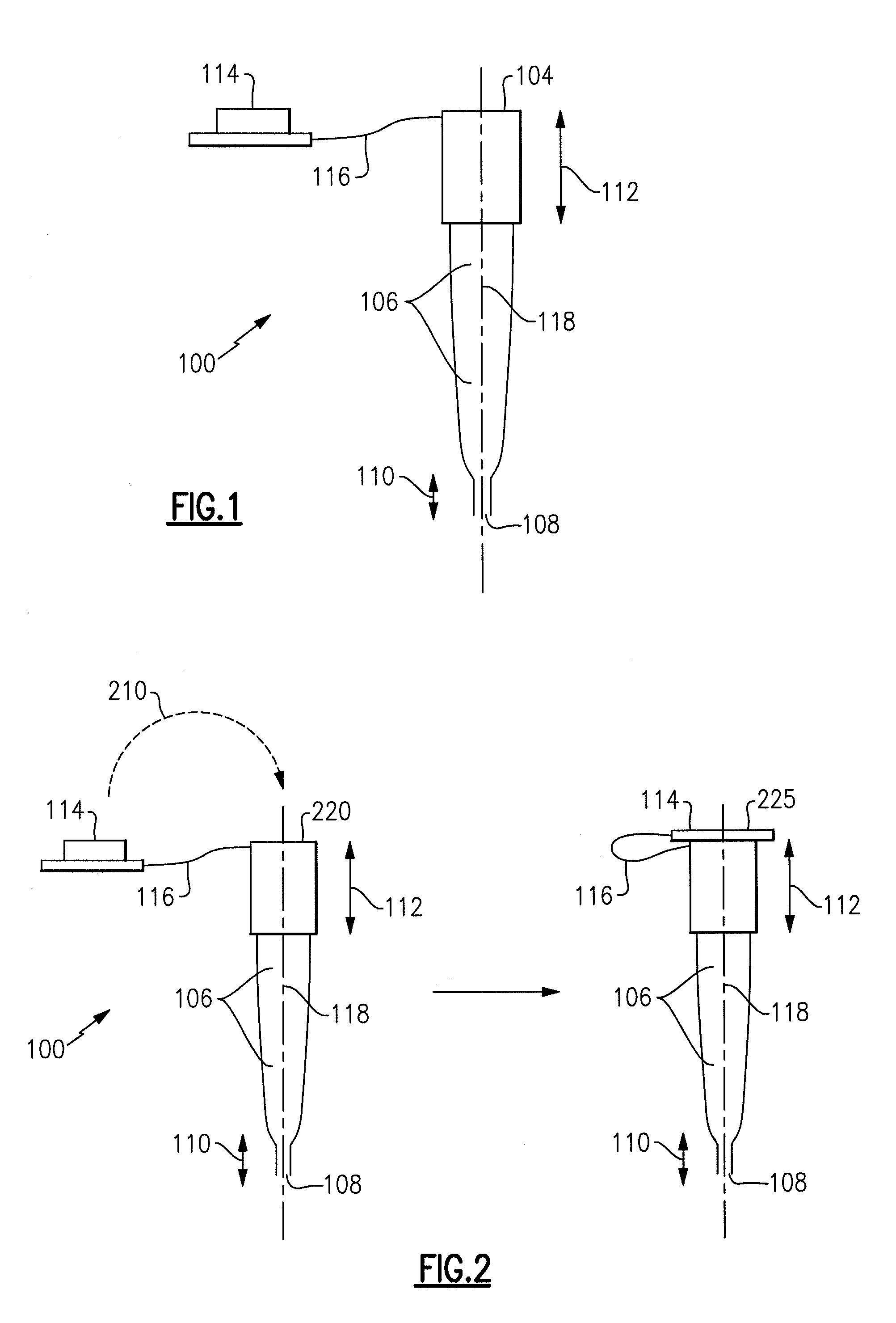
[0081] FIG. 1 shows a sealable fluid aspirating / dispensing member 100 for sample collection and particle separation. The fluid aspirating / dispensing member 100 is typically composed of an injection-moldable, preferably transparent, thermoplastic material such as polypropylene, polyallomer, polyethylene terephthalate, co-polymers or blends of polymers or any other suitable inert material known in the art. Preferably, the sample being analyzed does not adhere to the walls of the internal volume of the fluid aspirating / dispensing member 100 wherein these surfaces of the fluid aspirating / dispensing member 100 may be treated to avoid such adherence of the sample or reagents to the internal surfaces of the fluid aspirating / dispensing member 100. The internal volume of a fluid aspirating / dispensing member 100 may be from about 1 microliter to about 2000 microliters or more. In one example, the internal volume is from about 1 microliter to about 500 microliters. In a preferred embodiment, t...
second embodiment
[0084]With the foregoing structural description of a fluid aspirating / dispensing member 100, a method is now described with respect to sample collection and particle separation within a fluid aspirating / dispensing member 100 in accordance with a
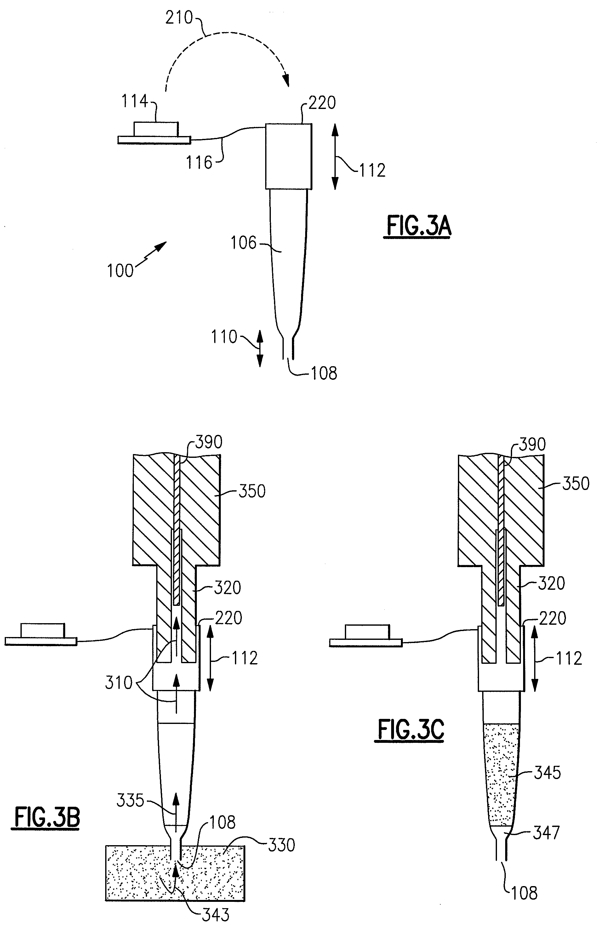
[0085]Referring to FIG. 3B, the fluid aspirating / dispensing member 100 is shown as attached to a metering mechanism 350 and more specifically a proboscis 320 of a clinical analyzer. The proboscis forms a component of a metering mechanism of the analyzer. Appropriate robotic commands direct the metering system to align the proboscis 320 with the input port 220 of the fluid aspirating / dispensing member 100. After proper alignment, the metering system hermetically inserts the proboscis 320 through the open input port 220 into the proboscis receptacle region 112 of the fluid aspirating / dispensing member 100. The input port 108 is then immersed into the sample 330. The proboscis 320 of the metering mechanism 350 creates a controlled amount of nega...
third embodiment
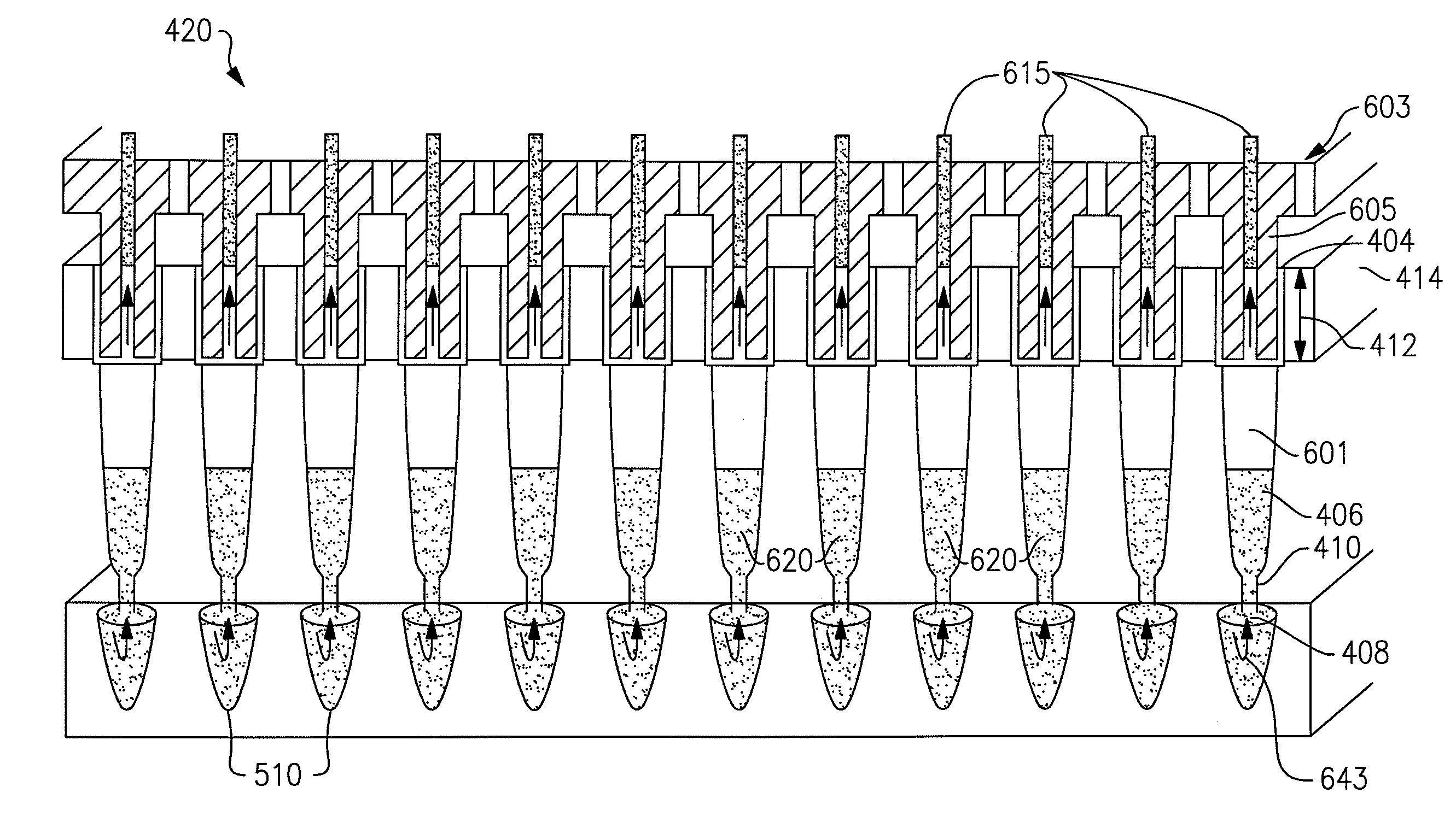
[0094]In accordance with a third embodiment, FIGS. 4A and 4B illustrate a fluid aspirating / dispensing member assembly configuration that is more amenable to automation and high throughput analysis of a plurality of samples. FIG. 4A depicts a fluid aspirating / dispensing plate 400 on which 96 of the fluid aspirating / dispensing members 100 of FIG. 1 are arranged into 8 rows of 12 fluid aspirating / dispensing members 425. FIG. 4B portrays a cross sectional view of the plate 400 to show row 420 of 12 fluid aspirating / dispensing members 425 attached to a solid support 414. In one version, the attachment may be reversible. Each of the aspirating / dispensing members 425 comprises an input port 404, proboscis receptacle region 412 attached to a solid support 414, a sample cavity 406, a sealable cavity 410 and sealable input port 408. FIG. 5 illustrates how the sealable input ports 408 of the fluid aspirating / dispensing plate 400 can align with the wells 510 of a microtiter plate 500.
PUM
 Abstract
Description
Claims
Application Information