Conditioner for Chemical Mechanical Planarization Pad

a technology of mechanical planarization and conditioner, which is applied in the direction of grinding drive, grinding drive, manufacturing tools, etc., can solve the problems of inability to play the role of the pad surface, uneven surface of the pad, and inability to meet the needs of the industry, so as to achieve uniform dressing, superior dressing efficiency and performance reproducibility

Inactive Publication Date: 2010-01-21
AN JUNG SOO +2
View PDF14 Cites 52 Cited by
  • Summary
  • Abstract
  • Description
  • Claims
  • Application Information

AI Technical Summary

Benefits of technology

[0023]The present invention has been made to solve the foregoing problems of the prior art and it is therefore an object of the present invention to provide a conditioner for CMP pad capable of achieving uniform dressing and superior dressing efficiency and performance reproducibility by arranging abrasive particles by proper size, by proper form and in a proper position, maintaining a uniform gap without abrasive particles being biased and at the same time ensuring a desired particle size distribution of abrasive particles in a predetermined ratio in the conditioner.

Problems solved by technology

However with higher integration of elements and reduced minimum width of wiring, the semiconductor industry has encountered limitations the conventional local planarization technology cannot overcome.
However, during polishing, pressure and relative speed are added, and thus with process time passing, the surface of pad becomes uneven and fine pores on the polishing pad are glazed by abrasive remnants, no longer capable of playing their role.
Subsequently, global planarization across wafer surface and uniform polishing on wafers during the whole process can not be accomplished.
Out of the methods of arranging abrasive particles, the random arrangement, as shown in FIG. 1, does not allow precise control of the number of abrasive particles 11 which are contained in a conditioner 10, thus unlikely to achieve reproducibility of design and performance.
Furthermore, for the random arrangement, a uniform gap of abrasive particles cannot be maintained, possibly causing abrasive particles to be locally biased in the conditioner.
In this case, a pad goes through uneven wear, resultantly deteriorating profile or uniformity of wafer to be polished.
However, with a significant increase in the number of abrasive particles being involved in a dressing, the abrasive particles cannot deeply penetrate the pad, resultantly deteriorating dressing effects.
But in case of manufacturing the conditioner according to the conventional patterning method, a predetermined ratio of bigger and smaller abrasive particles is hardly maintainable.
As a result, the conventional patterning method has limitations in realizing superior reproducibility.
Moreover, according to the conventional patterning method, in case where bigger abrasive particles or relatively smaller abrasive particles are biased in a certain region, abrasive particles of a certain region are involved in the dressing, while those of another region are not, leading to uneven wear of the pad.
As a result, superior profile of wafer may not be obtainable.

Method used


Image

  • Conditioner for Chemical Mechanical Planarization Pad
  • Conditioner for Chemical Mechanical Planarization Pad
  • Conditioner for Chemical Mechanical Planarization Pad

Examples


example 1

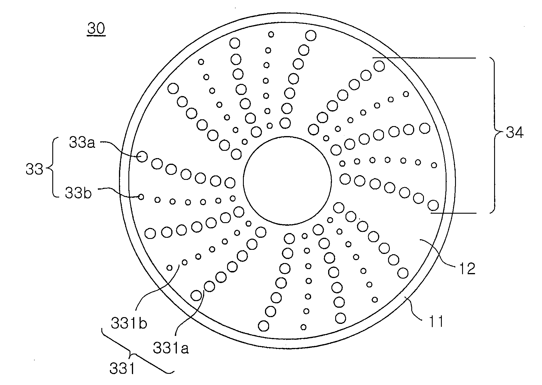
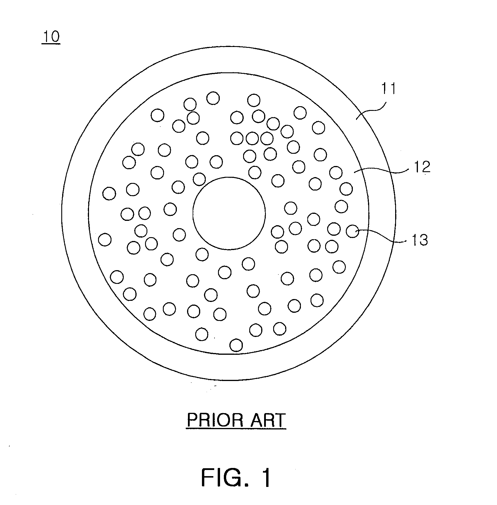
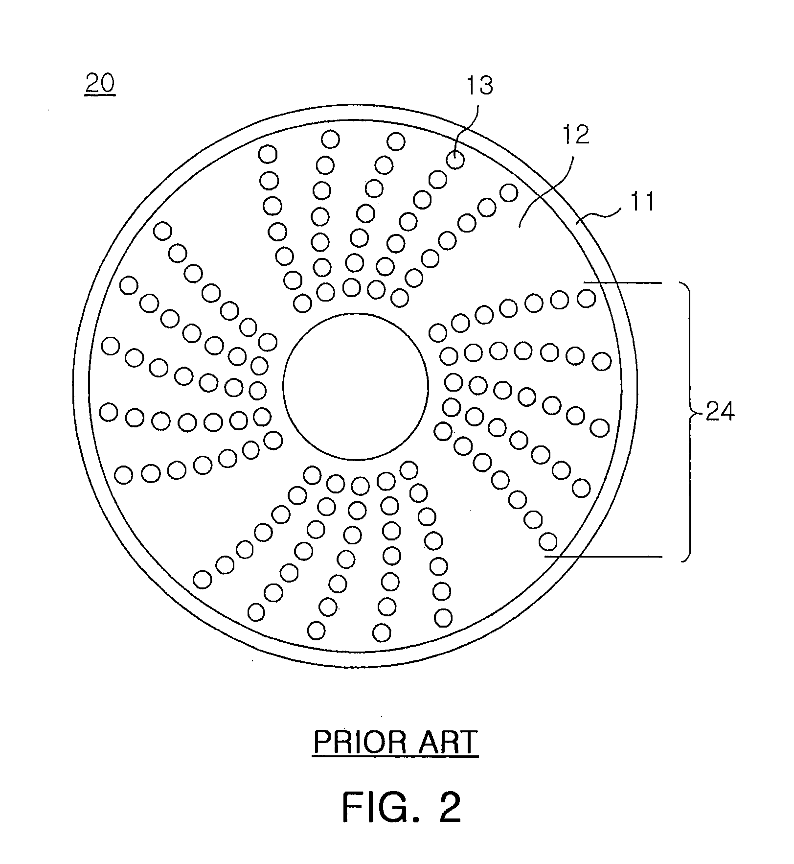
[0084]The products prepared include a conditioner of random arrangement having abrasive particles without size difference randomly arranged (conventional product 1), a conditioner of conventional patterning having abrasive particles without size difference regularly arranged (conventional product 2), a conditioner of the invention having at least 2 abrasive particles with size difference alternately attached in a row to a segment (inventive product 1), a conditioner of the invention having at least 2 abrasive particles with size difference alternately attached to each segment (inventive product 2), and a conditioner of the invention having abrasive particles attached in a row forming a circle (inventive product 3).

[0085]With respect to the conventional conditioner and the conditioner of the invention, an evaluation was conducted on cut rate of pad and fracture of abrasive particles. The results are shown in table 1.

TABLE 1Evaluation resultsFracture orPad cut rate (μm / hr)pulling out ...

example 2

[0089]The products prepared include a conditioner (comparative product 1) representing less than 10% size difference between bigger and smaller abrasive particles, a conditioner (inventive product 4) having abrasive particles with 10 to 40% of size difference and a conditioner (comparative product 2) having abrasive particles with 45 to 70% of size difference. The products have bigger and smaller abrasive particles in a row at a predetermined rate.

[0090]For the conditioners manufactured as just described, wafer removal rate was measured on a time basis and the results are shown in table 2 below.

TABLE 2Wafer removal rate (Å / min)20401 hourhourshoursAveragevariationComparative3642328727693233873product 1Inventive product 43685351433973532288Comparative39913102255432151437product 2

[0091]As shown in Table 2, for comparative product 1 having abrasive particles with less than 10% size difference, wafer removal rate after 40-hour use drops significantly from the initial removal rate.

[0092]T...

example 3

[0097]Manufactured were conditioners having bigger abrasive particles, mid-sized abrasive particles and smaller abrasive particles with 10-40% of overall size difference arranged in a row. With respect to the conditioners, an evaluation was conducted on cut rate of pad and the results are shown in Table 3 below.

[0098]In Table 3 below, inventive product 5 is a conditioner having bigger abrasive particles A, mid-sized abrasive particles B and smaller abrasive particles C arranged successively in a row. Inventive product 6 is a conditioner having bigger abrasive particles A, smaller abrasive particles C and mid-sized abrasive particles B arranged successively in a row. Conventional product 1 is a conditioner having abrasive particles without size difference arranged randomly.

TABLE 3Pad cut rate (μm / hr)1st2nd3rdAveragevariationInventive product 545744946145612Inventive product 645545744045117Conventional product 132235729832559

[0099]As shown in table 3, if abrasive particles have 10 to ...


PUM

PropertyMeasurementUnit
abrasiveaaaaaaaaaa
diameteraaaaaaaaaa
sizesaaaaaaaaaa

Abstract

The present invention provides a conditioner for CMP pad required for global planarization of wafer to achieve high integration of a semiconductor element. The conditioner for CMP pad includes a metal substrate having abrasive particles fixed thereto, a plurality of abrasive particles fixed to the metal substrate, and a layer of metal binder fixing the abrasive particles to the metal substrate. The abrasive particles include at least one pattern. The pattern includes at least one row of abrasive particles and the abrasive particles include bigger abrasive particles and smaller abrasive particles. In addition, a diameter difference between smaller and bigger abrasive particles is 10 to 40%. The present invention ensures uniform dressing of conditioner, superior dressing efficiency and superior performance reproducibility.

Description

CLAIM OF PRIORITY[0001]This application claims the benefit of Korean Patent Application No. 2004-105068 filed on Dec. 13, 2004, in the Korean Intellectual Property Office, the disclosure of which is incorporated herein by reference.BACKGROUND OF THE INVENTION[0002]1. Field of the Invention[0003]The present invention relates to a conditioner for Chemical Mechanical Planarization (CMP) pad required for global planarization of wafer to achieve high integration of a semiconductor element. More particularly, the present invention relates to a conditioner for CMP pad in which the arrangement of abrasive particles is properly controlled.[0004]2. Description of the Related Art[0005]These days, the semiconductor industry experiences high-speed and high-integration in circuits, and with integration capacity enlarged increasingly, chip size becomes bigger. To overcome the resultant limitations, the industry has undergone structural changes such as minimized width of wiring, larger diameter of ...

Claims


Application Information

Patent Timeline
Patent Type & Authority Applications(United States)
IPC IPC(8): B24B53/02
CPCB24B53/017B24B53/12H01L21/304
Inventor AN, JUNG SOOLEE, JOO HANKWACK, KYOUNG KUK
Owner AN JUNG SOO
Why Eureka
Try Eureka