Method and system for generating a control system user interface

a technology of user interface and control system, applied in the direction of electric digital data processing, instruments, computing, etc., can solve the problems of delay, plant shutdown or accident, loss of seconds, delay or even loss of relevant technical information,

a technology of user interface and control system, applied in the direction of electric digital data processing, instruments, computing, etc., can solve the problems of delay, plant shutdown or accident, loss of seconds, delay or even loss of relevant technical information,

US20100017746A1Active Publication Date: 2010-01-21ABB (SCHWEIZ) AG

Image

  • Method and system for generating a control system user interface
  • Method and system for generating a control system user interface
  • Method and system for generating a control system user interface

Examples


Embodiment Construction

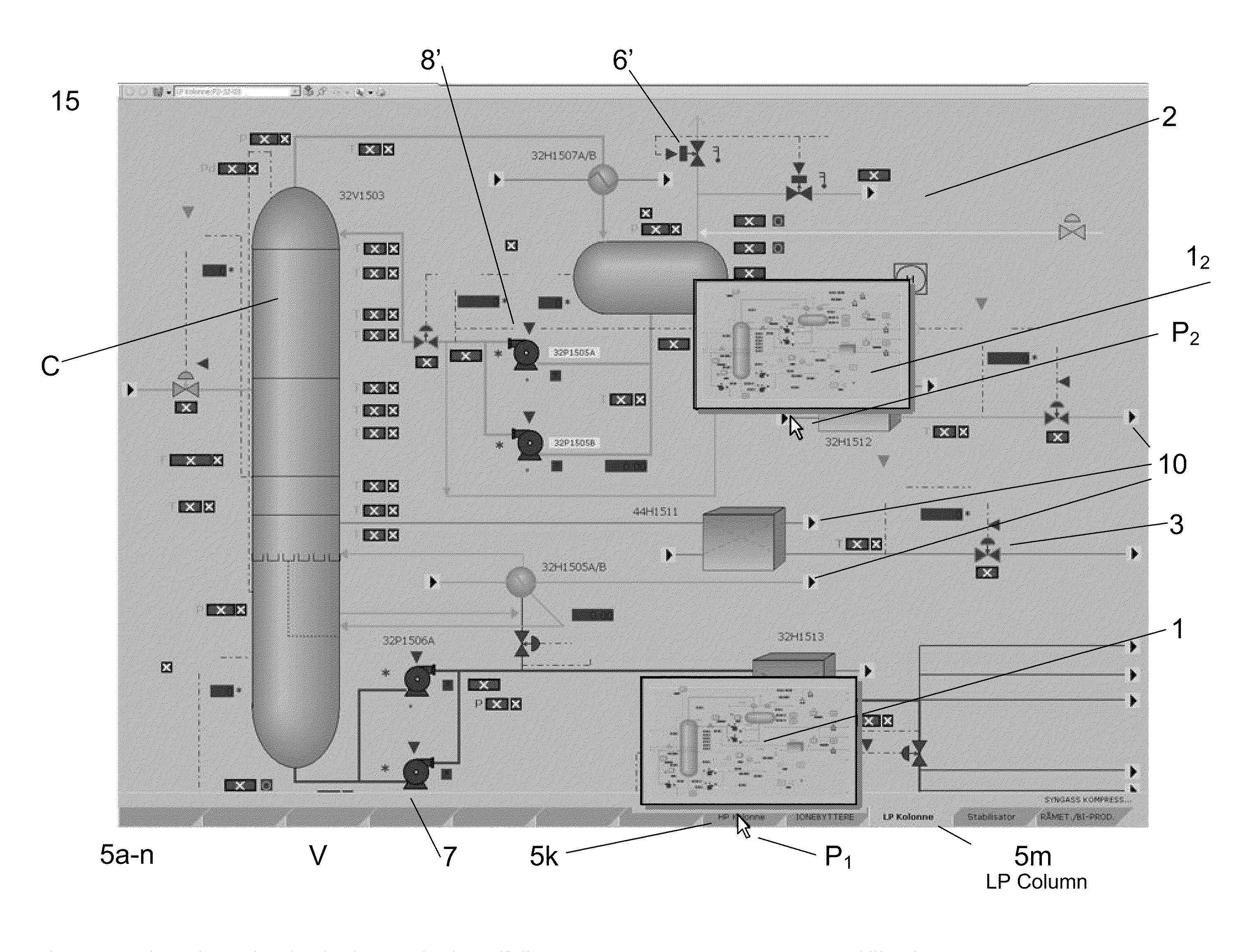
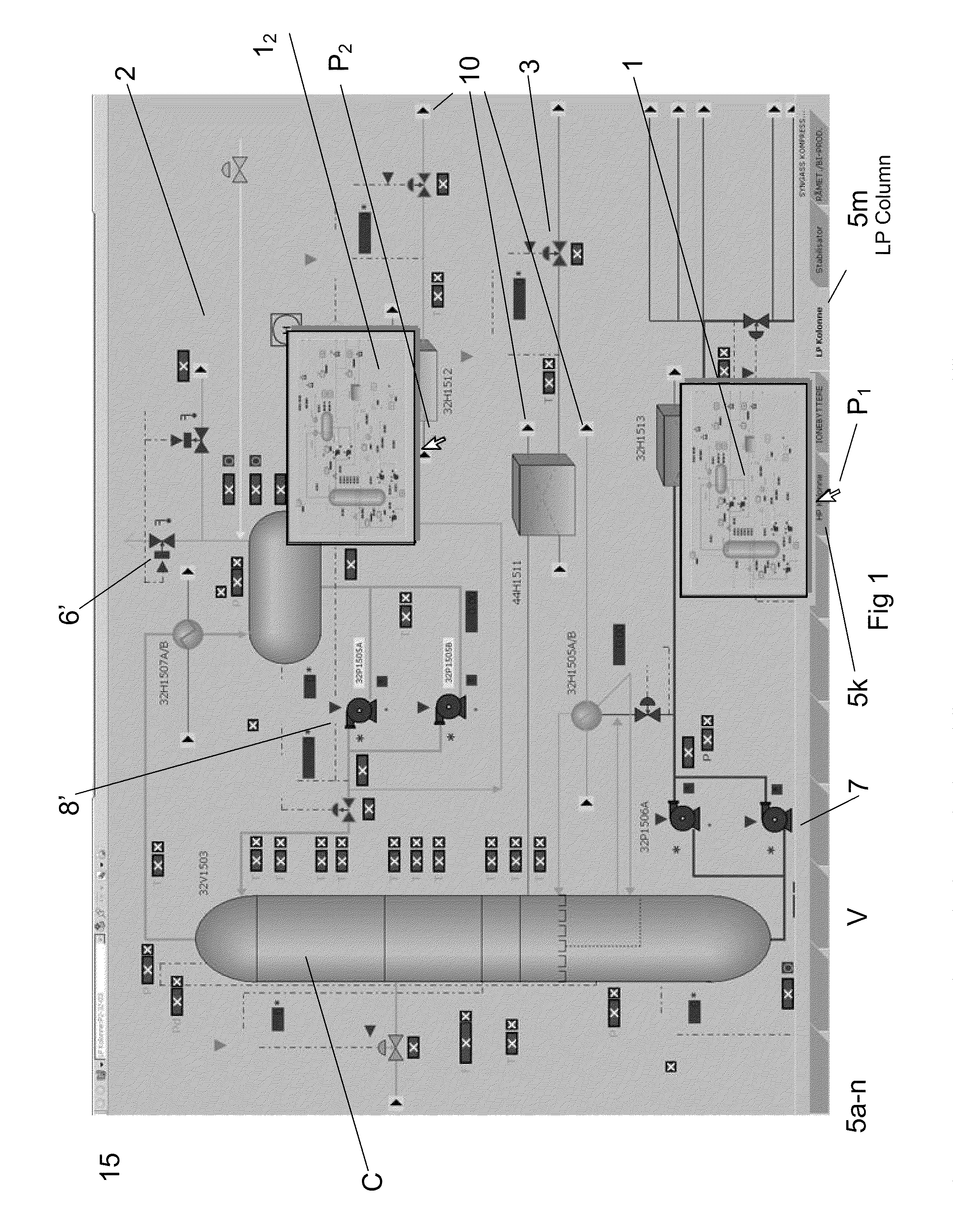
[0052]This invention describes a system for and a method of generating technical information comprising both static and dynamic data in industrial supervision, maintenance and control for navigation and control purposes. The trend towards operation from remote operation centres introduces an increase in both the control room operators' work domain and the workload as several different processes can be supervised and controlled in parallel.

[0053]FIG. 1 shows a graphical user interface display 15 of an industrial control system. FIG. 1 shows a schematic of a process section, in this case for an oil and gas processing facility. The process section shown as an example comprises a process graphic 2 which contains many control objects including a HP Column C, a pump 7, a motorised valve 6′, a pump 8′ and a second valve 3. The process graphic 2 shown is a member of a predetermined group of process graphics, a logical grouping based on relationships to one or more technical functions in the...


PUM


Abstract

A method for providing a user interface for an industrial control system including a computer and a plurality of process graphics including software objects for controlling and / or monitoring real world objects controlled by the control system. A display of selected process graphics, a designated view arranged with a tab or another selector, is automatically generated. The designated view may be generated dependent on selecting one or more logical groupings to which control system software objects representing the real world objects belong. At least one tab on a designated view, or an active link, is arranged to display a small visual representation of a second process graphic to which it is linked on detection of a computer input on or near the at least one tab, or link.

Description

TECHNICAL FIELD[0001]The invention concerns method and system for automatically providing a user interface in an industrial control system. In particular the invention is a user interface with improved tools for selection of process graphics and for navigation between them.TECHNICAL BACKGROUND[0002]In the supervisory control of industrial plants there is continual requirement for information about equipment, current and historic process data, trends, etc. This information is typically provided by the control system and usually in the form of one or more distributed control systems (DCS) and / or supervisory control and data acquisition (SCADA) systems. The information is often presented to the operators through a display screen showing a process graphic that presents process data (measurements, values), tag identifiers, equipment ID, alarm status, connections between plant equipment, etc. As more and more data is being presented to the operators, the visual user interfaces often hold ...

Claims


Application Information

Patent Timeline
21 Jan 2010
Publication
US20100017746A1
IPC
G06F3/048; G05B15/00
CPC
G06F3/0484; G06F9/4443; G06F9/451; G06F3/0481
Inventors
HUSOY, KRISTOFFER; GRAVEN, TONE-GRETE