Microfluidic system and method for manufacturing the same
a microfluidic system and actuator technology, applied in the field of microfluidics, can solve the problem of faster process completion tim
- Summary
- Abstract
- Description
- Claims
- Application Information
AI Technical Summary
Benefits of technology
Problems solved by technology
Method used
Image

Examples
example 1
Prototype Microfluidic Systems
[0165]Prototype microfluidic systems, about 50 μm in height were manufactured according to the teachings of some embodiments of the present invention.
[0166]The prototype microfluidic systems were fabricated in PDMS by soft lithography. The production procedure is illustrated in FIG. 6.
[0167]A silicon wafer was cleaned, spun coated with SU-8 negative photoresist, soft baked, exposed to UV light through a transparency film mask and baked again. Development resulted in a master mold containing the microchannel network pattern in relief. The master was used as a bottom mold. After silanization with trimethylchlorosilane (Sigma Aldrich) the master was pressed against a Teflon mold.
[0168]A custom-made metal cylinder with four 1×1 mm extensions was placed on the mold above one of the microchannels to define a PDMS membrane. The length of the four extensions determines the width of the membrane. After PDMS degassing and curing, the cylindrical insert was pulled...
example 2
Droplet Generation
[0172]The prototype microfluidic systems described in Example 1 were used for generation of water droplets in oil.
Methods
[0173]A custom made aluminum frame was constructed in order to hold the prototype systems on the microscope. The piezoelectric actuator stack was fastened to a stainless steel arm which was bolted to the aluminum frame, so as to allow controlling the position and angle of the actuator.
[0174]The voltage signal applied to the actuator was generated using an MDT683A open loop piezo controller (Thorlabs, USA) which was modulated using a signal generator (3320A, Agilent USA). A scope (TDS 1002, Tektronix USA) was connected to the signal generator in order to monitor the output voltage.
[0175]Pressure driven flow was applied using gravity. Two containers, one filled with filtered oleic acid (Sigma, USA) and the other with DI water were positioned at a fixed height during the experiments. It was thus possible to instantly reach equilibrium between the wa...
example 3
Sorting
[0193]A prototype microfluidic system was manufactured as described in Example 1 and used for sorting objects, such as, but not limited to, particles and cells. The microchannel configuration and sorting procedure are schematically illustrated in FIGS. 14A and 14B.
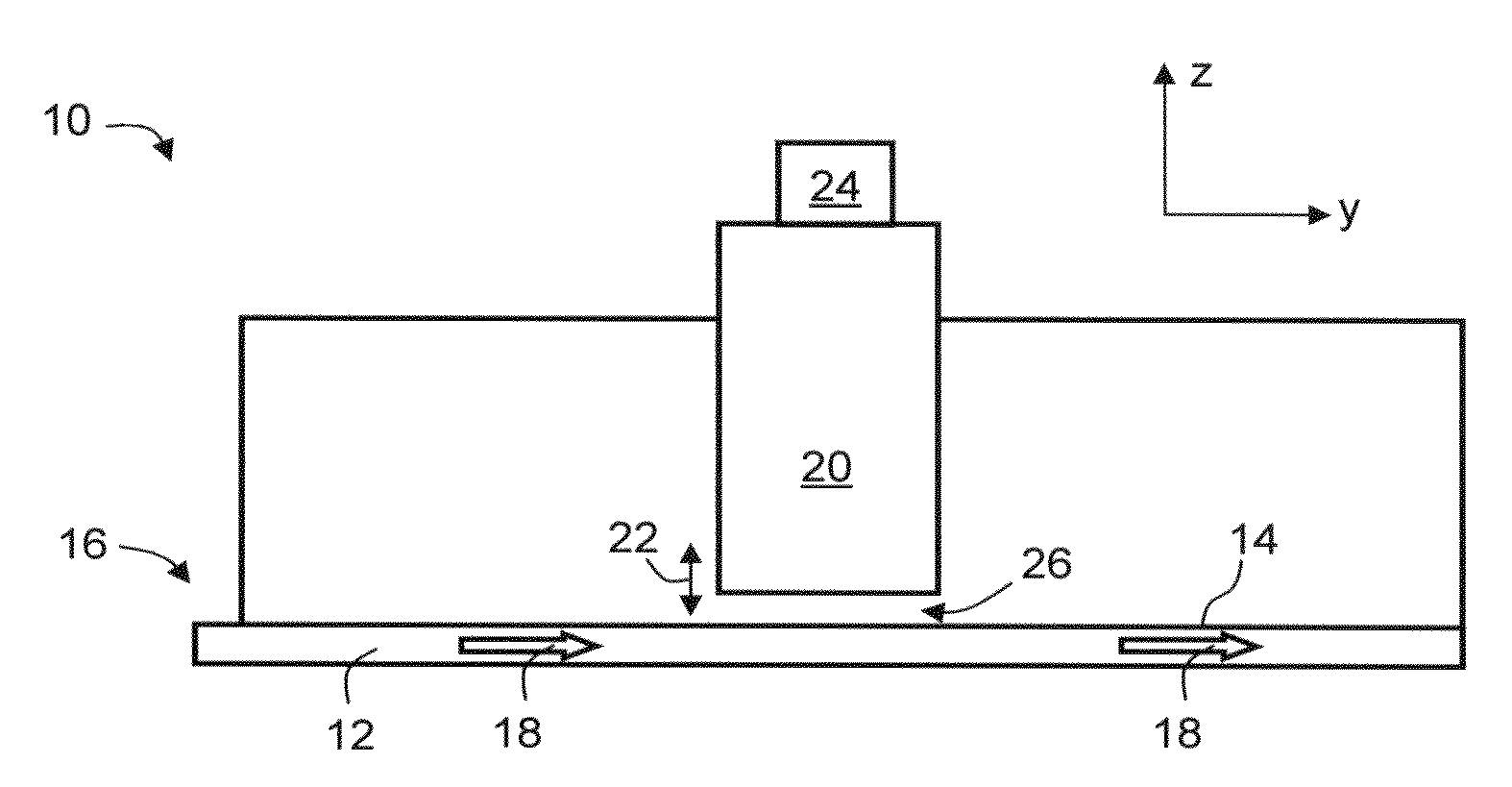
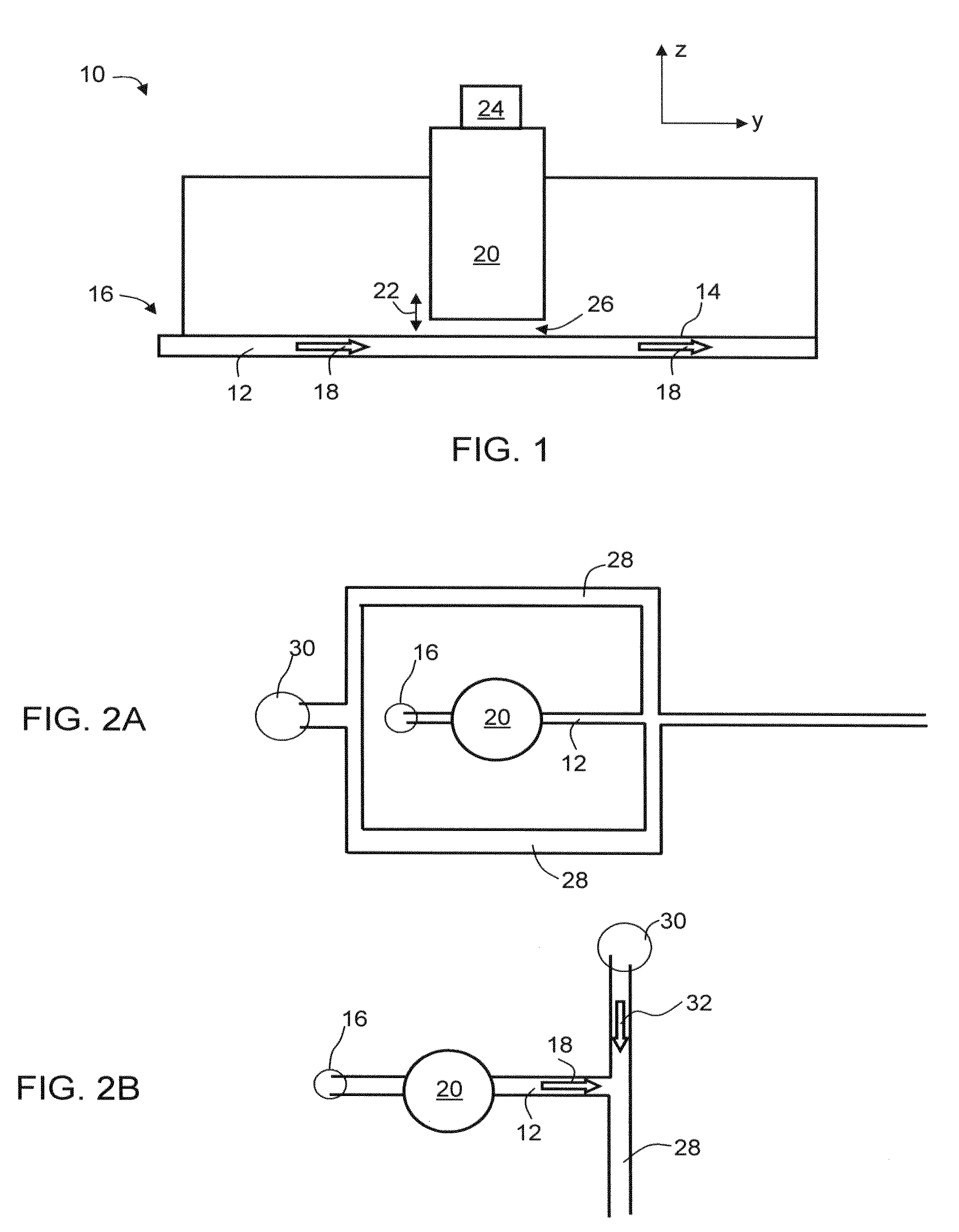
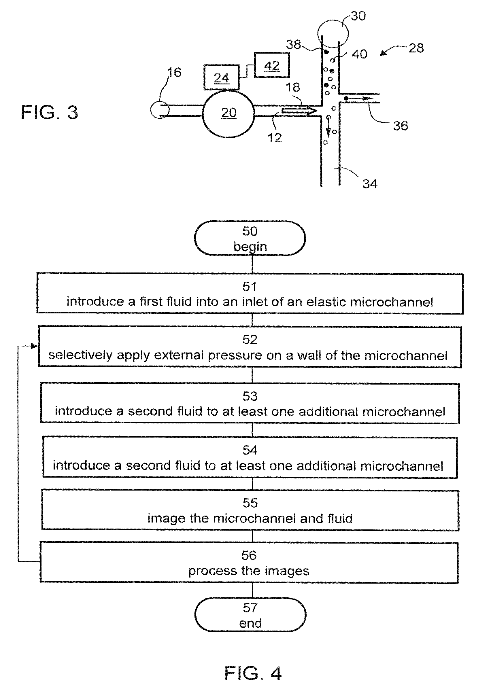
[0194]The prototype microfluidic system included a main microchannel 34, and two branch microchannels 12 and 36. The actuator (not shown, see FIG. 6) was mounted above microchannel 12, and was configured to apply external pressure on the elastic wall thereof. The resistance to flow characterizing main microchannel 34 was lower than the resistances to flow characterizing branch microchannels 12 and 36.
[0195]The prototype system also included CCD camera (not shown, see, e.g., imaging system 42 in FIG. 3) and a controller (not shown see, e.g., 24) which was configured for processing the images of the CCD camera and activating and deactivating the actuator based on the processing.
[0196]In FIG. 14A, a suspension of red b...
PUM
| Property | Measurement | Unit |
|---|---|---|
| Fraction | aaaaa | aaaaa |
| Pressure | aaaaa | aaaaa |
| Dispersion potential | aaaaa | aaaaa |
Abstract
Description
Claims
Application Information
 - Generate Ideas
- Intellectual Property
- Life Sciences
- Materials
- Tech Scout
- Unparalleled Data Quality
- Higher Quality Content
- 60% Fewer Hallucinations
Browse by: Latest US Patents, China's latest patents, Technical Efficacy Thesaurus, Application Domain, Technology Topic, Popular Technical Reports.
© 2025 PatSnap. All rights reserved.Legal|Privacy policy|Modern Slavery Act Transparency Statement|Sitemap|About US| Contact US: help@patsnap.com