Countercurrent direct-heating-type heat exchanger

a heat exchanger and countercurrent technology, applied in the field of countercurrent directheating type heat exchangers, can solve the problems of reducing the temperature in the autoclave, affecting the efficiency of heat exchange, so as to prevent local abrasion of the members, reduce the drift, and reduce the effect of heat exchang

Active Publication Date: 2010-01-28
SUMITOMO METAL MINING CO LTD
View PDF1 Cites 16 Cited by
  • Summary
  • Abstract
  • Description
  • Claims
  • Application Information

AI Technical Summary

Benefits of technology

[0016]The present inventors have found, after having intensively studied the above countercurrent direct-heating-type heat exchanger to attain the above object, that a feed nozzle having a specific shape and dimension and further an umbrella-type dispersing plate equipped with impingement projections and a weir having a specific shape on the top face, can suppress the drift when a fluid to be heated is supplied, and can control a uniform stream flowing downward radially on the slope of the umbrella-type dispersing plate and thus can prevent local abrasion of the members and also can carry out efficient heat exchange, and have completed the present invention.
[0032]The countercurrent direct-heating-type heat exchanger of the present invention solves the problems of conventional countercurrent direct-heating-type heat exchangers in a countercurrent direct-heating-type heat exchanger wherein heat exchange is carried out, while making a fluid to be heated inflow from its top and outflow from its bottom, and at the same time, making a heating medium inflow from its bottom and outflow from its top, and is able to suppress the drift in the case when a fluid to be heated is supplied, to prevent local abrasion of the members and also to carry out efficient heat exchange, and therefore, is very valuable in industries.

Problems solved by technology

On the other hand, because the ore slurry produced in the previous step is usually prepared under a temperature condition of around outdoor temperature, the ore slurry not only lowers the temperature in the autoclave but also makes stable leaching reaction difficult when it is charged to the autoclave as it is.
In this time, when the ore slurry is simply heated in order to raise stepwise the temperature of ore slurry, the fluidity of ore slurry deteriorates as the water in the ore slurry evaporates, resulting in insufficient leaching reaction in the autoclave.
These devices, however, usually have a problem that mechanical failures of the driving unit occur frequently or that indirect heating makes the structure of the device complicated, and thus are not always suitable as the heating method that satisfies the condition for heating while keeping its water content of ore slurry in good condition as described above, in a smelting plant where a large amount of ore material is treated, like the above wet process of smelting.
Typical equipment trouble that occurs on a regular basis, however, includes an abrasion of each internal member due to the ore slurry.
However, there has been a problem that an ore slurry and steam begin to leak unexpectedly through a hole generated in the side wall of the main body of a countercurrent direct-heating-type heat exchanger or that local decrease in thickness of the relevant side wall is found in a large-scale periodical inspection accompanied by shutdown of operation to be conducted usually every half a year.
The above situation, especially the outbreak of unexpected leak, requires great cost and time for repairing the relevant damaged part and causes not only the shutdown of the preheating step but also substantial reduction of the plant utilization rate in the whole operation of smelting.
In addition, when the ore slurry drifts, the contact area between the ore slurry and steam becomes smaller than the area when the ore slurry forms a uniform stream flowing downward radially on the slope of the umbrella-type dispersing plate, which results in reduced efficiency of heat exchange and increased operation cost.

Method used


Image

  • Countercurrent direct-heating-type heat exchanger
  • Countercurrent direct-heating-type heat exchanger
  • Countercurrent direct-heating-type heat exchanger

Examples


example 1

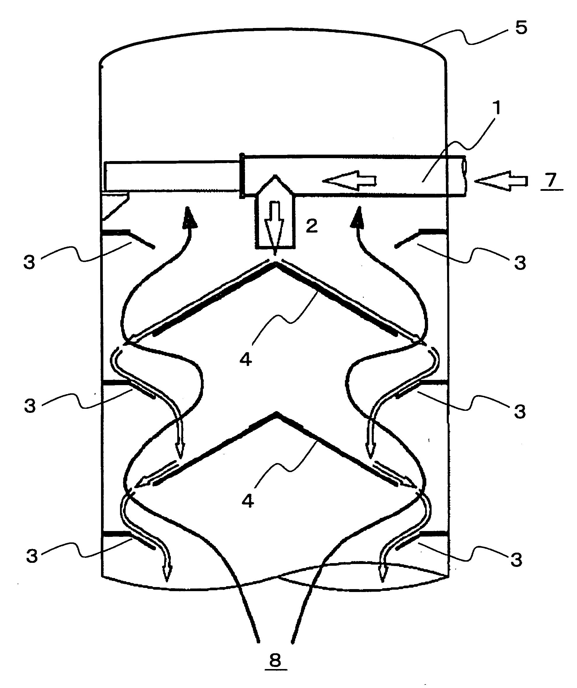
[0064]The first embodiment of the present invention is a countercurrent direct-heating-type heat exchanger wherein, heat exchange is carried out, while making a fluid to be heated 7 inflow from its top into an upright nearly-cylindrical vessel 5 equipped internally with parts including the following (A) to (D), and making the fluid outflow from its bottom, and at the same time, making a heating medium 8 inflow from its bottom and making the medium outflow from its top:[0065](A) a feed pipe for the above fluid to be heated located at the diameter of the horizontal cross section at the top of the above nearly cylindrical vessel 5,[0066](B) a feed nozzle 2 for the above fluid to be heated 7 having an opening at its bottom end in the vertical direction which is connected with the above feed pipe 1 at the center of the above horizontal cross section,[0067](C) a plurality of ring-like straightening plates 3 located on the circumference of the inner surface of the side wall of the above ne...

example 2

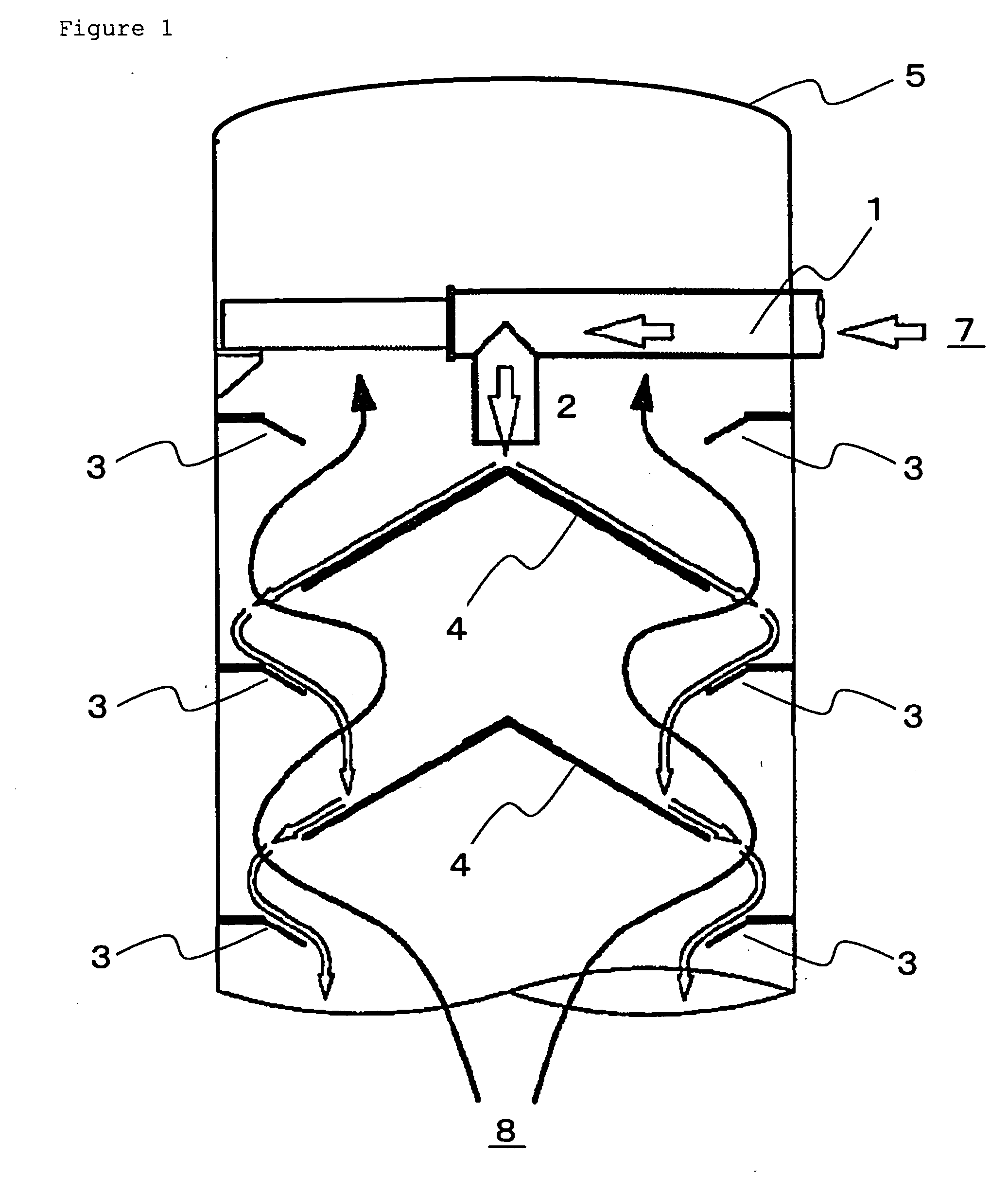
[0077]The second embodiment of the present invention is characterized in that the feed nozzle 2 has a double pipe structure having the closed center part and opened circumference in its open cross section in the above first embodiment, as shown in FIG. 2. FIG. 2 is a schematic view of a feed nozzle having a double pipe structure representing one example of the feed nozzle of the present invention.

[0078]That is, the flow rate of a fluid to be heated flowing inside a pipe becomes generally large at the center of the cross section of the pipe having a circular cross section. Therefore, the fluid to be heated to be supplied to the apex of the umbrella-type dispersing plate is supplied as a nearly cylindrical stream by the feed nozzle 2 having a double pipe structure and the apex of the umbrella-type dispersing plate 4 is located nearly at the center of the cylindrical stream. Consequently, the fluid to be heated is supplied by more uniform flow rate than in the above first embodiment.

[0...

example 3

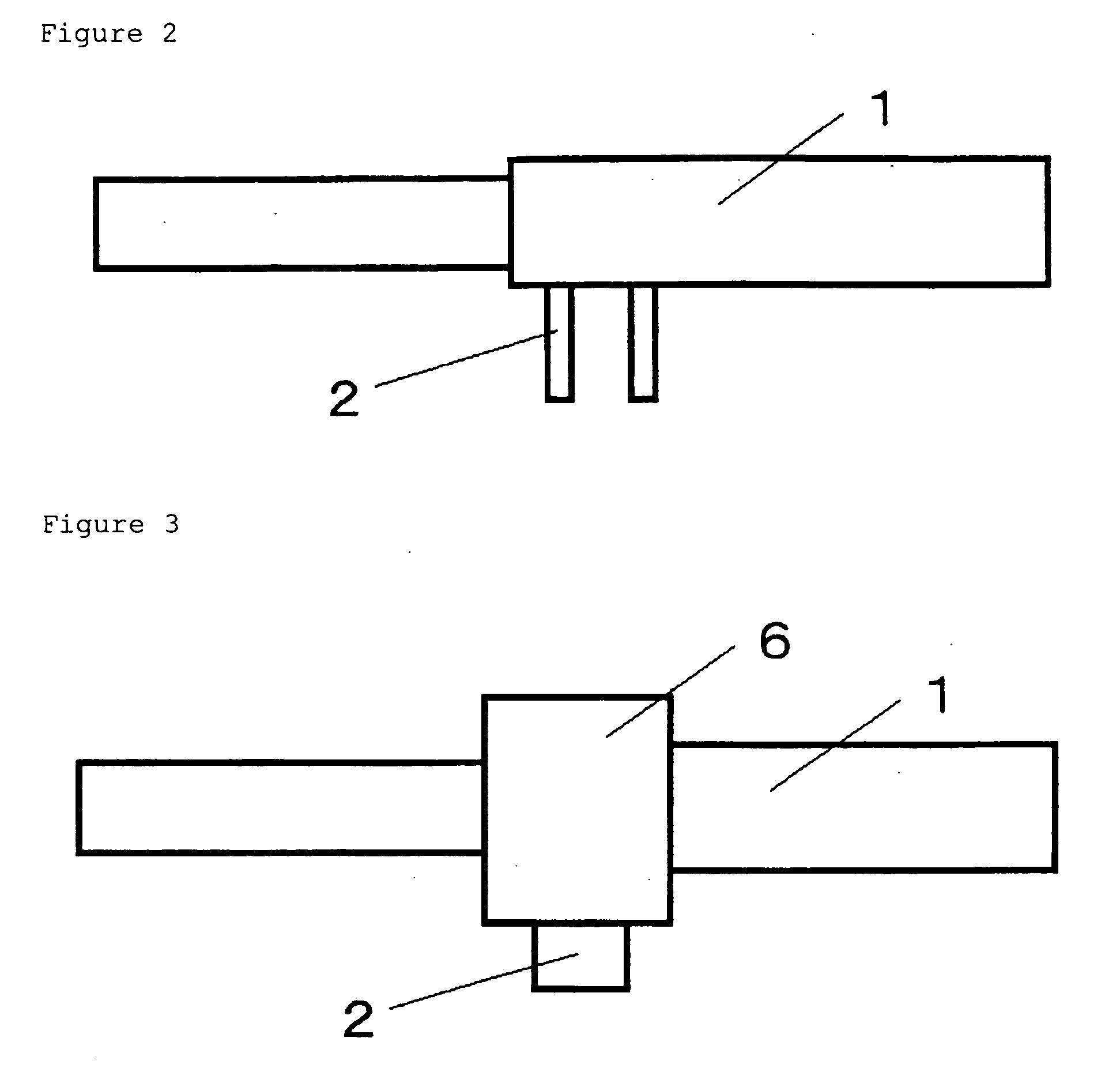
[0080]The third embodiment of the present invention is characterized in that a storing chamber 6 of a fluid to be heated is installed between the above feed pipe 1 and feed nozzle 2 in the above first embodiment, as shown in FIG. 3. FIG. 3 is a schematic view of a feed nozzle having a storing chamber of a fluid to be heated representing one example of the feed nozzle of the present invention.

[0081]That is, the stream of a fluid to be heated generally tends to become turbulent at the bend of piping, resulting in an uneven flow rate. Therefore, the storing chamber 6 installed at the connecting part of the feed pipe 1 and the feed nozzle 2 can prevent the stream of the fluid to be heated in the feed pipe 1 from flowing directly into the feed nozzle 2 and from becoming turbulent, consequently, the fluid to be heated is supplied to the umbrella-type dispersing plate at the more uniform flow rate than in the above first embodiment.

[0082]Here, the volume of the storing chamber is not parti...


PUM

PropertyMeasurementUnit
diameteraaaaaaaaaa
diameteraaaaaaaaaa
temperatureaaaaaaaaaa

Abstract

The countercurrent direct-heating-type heat exchanger that is able to suppress drift in the case when a fluid to be heated is supplied, to prevent local abrasion of the members and also to carry out efficient heat exchange.The countercurrent direct-heating-type heat exchanger equipped with a feed pipe, a feed nozzle, ring-like straightening plates and umbrella-type dispersing plates of the above fluid to be heated, characterized in that the above feed nozzle has the shape of a pipe having a circular cross section and the dimension satisfying the following formula (1) and formula (2):Ln / Dn≧1   Formula (1)(wherein, Ln indicates the length of the feed nozzle; and Dn indicates the inside diameter of the feed nozzle)1.5≦Sp / Sn≦2.0   Formula (2)(wherein, Sp indicates the inner cross-sectional area of the feed pipe; and Sn indicates the inner cross-sectional area of the feed nozzle).

Description

BACKGROUND OF THE INVENTION[0001]1. Field of the Invention[0002]The present invention relates to a countercurrent direct-heating-type heat exchanger, in more detail, to a countercurrent direct-heating-type heat exchanger that is able to suppress the drift in the case when a fluid to be heated is supplied, to prevent local abrasion of the members and also to carry out efficient heat exchange, wherein heat exchange is carried out, while making a fluid to be heated inflow from its top and outflow from its bottom, and at the same time, making a heating medium inflow from its bottom and outflow from its top. It should be noted that, the fluid to be heated is generally a material to be heated having fluidity including, for example, a slurry fluid containing solid components.[0003]2. Description of the Prior Art[0004]A heat exchanger, wherein heat exchange is carried out to a heating medium, has been conventionally employed as a means for heating a fluid to be heat.[0005]A High Pressure Ac...

Claims


Application Information

Patent Timeline
Patent Type & Authority Applications(United States)
IPC IPC(8): C22B1/00F28F9/22
CPCC22B3/02F28C3/10F28C3/06Y02P10/20
Inventor JIN-NO, YOSHINORIOOTA, HIROKAZUSASAKI, YUKIHITOSUGANUMA, SHINSUKE
Owner SUMITOMO METAL MINING CO LTD
Why Eureka
Try Eureka