Projection exposure tool for microlithography with a measuring apparatus and method for measuring an irradiation strength distribution

a technology of microlithography and exposure tool, which is applied in the direction of optical radiation measurement, printers, instruments, etc., can solve the problems of insufficient information thus obtained regarding the course of electromagnetic radiation for the optimum coordination or adjustment of optical sub-systems, and achieve the effect of improving angular resolution, local resolution of radiation detectors, and reducing the number of radiation exposures

Inactive Publication Date: 2010-01-28
CARL ZEISS SMT GMBH
View PDF14 Cites 34 Cited by
  • Summary
  • Abstract
  • Description
  • Claims
  • Application Information

AI Technical Summary

Benefits of technology

[0030]Moreover, it is advantageous if the measuring apparatus furthermore has a first movement device for moving the radiation detector in the common image plane. Therefore, when recording the intensity of the electromagnetic radiation reaching the radiation detector, the radiation detector can be moved. Advantageously, the local resolution of the radiation detector is pixel-limited, and the first movement device is designed to move the radiation detector two-dimensionally during recording of the radiation reaching the radiation detector by up to ±1 pixel width of the radiation detector. Advantageously, the measuring apparatus further includes an evaluation device which is designed to push back and average the images recorded mathematically, and to establish the spot center points of the individual ray bundles hitting the recording surface of the detector using the focusing optical elements. This method is also called “dithering”. Therefore, the irradiation strength distribution can be established with improved angular resolution. For example, with this method, the spot center point with a wavelength of 193 nm can be established with 0.5 μm precision. The spot diameter with this wavelength is ideally 2 μm, but in practice this is increased by aberrations and is for example approx. 5 μm.
[0031]Furthermore, it is advantageous if a second movement device for moving the measuring appa

Problems solved by technology

However, the information thus obtained regarding the course of the electromagnetic radiation

Method used


Image

  • Projection exposure tool for microlithography with a measuring apparatus and method for measuring an irradiation strength distribution
  • Projection exposure tool for microlithography with a measuring apparatus and method for measuring an irradiation strength distribution
  • Projection exposure tool for microlithography with a measuring apparatus and method for measuring an irradiation strength distribution

Examples


Embodiment Construction

[0066]In the exemplary embodiments described below elements which are functionally or structurally similar to one another are provided as far as possible with the same or similar reference numbers. Therefore, in order to fully appreciate the features of the individual elements of a specific exemplary embodiment, reference should be made to the description of other exemplary embodiments or to the general description of the invention.

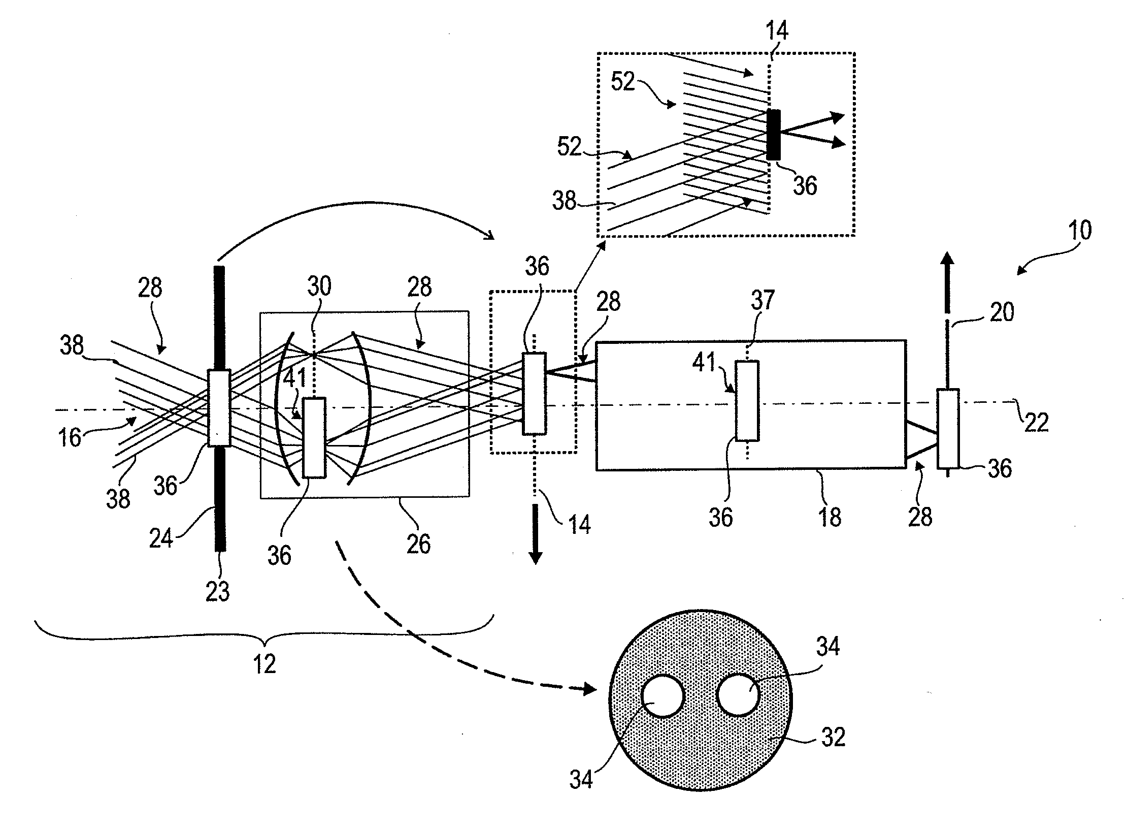
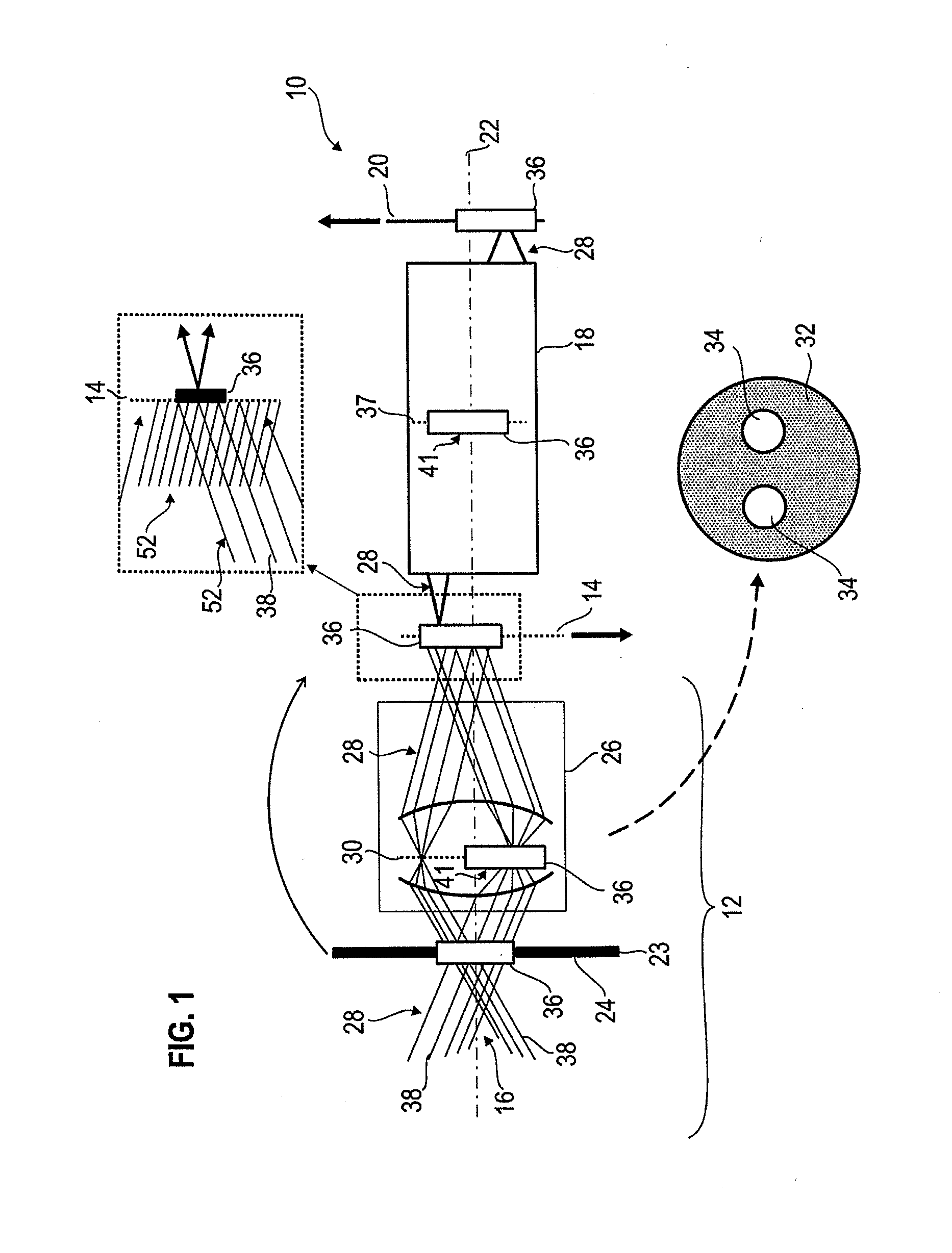
[0067]FIG. 1 shows an exemplary embodiment of a projection exposure tool 10 according to the invention for microlithography in the form of a scanner. The projection exposure tool 10 includes an illumination system 12 for illuminating a reticle disposed in a reticle plane 14 of the projection exposure tool 10. The reticle is not shown in FIG. 1. The reticle is illuminated with electromagnetic radiation with a specific wavelength which, depending on the type of projection exposure tool 10, can be in the UV wavelength range or in the EUV wavelength range (ex...


PUM


Abstract

A projection exposure tool (10) for microlithography with a measuring apparatus (36) disposed in an optical path (28) of the projection exposure tool (10) for the locally and angularly resolved measurement of an irradiation strength distribution. The measuring apparatus (36) includes a measuring field with an arrangement (56) of focusing optical elements (42) disposed at respective individual points of the measuring field (41), a common image plane (44) for the focusing optical elements (42), a locally resolving radiation detector (46) with a recording surface (48) for the locally resolved recording of a radiation intensity, the recording surface (48) being disposed in the common image plane (44), and the radiation detector outputting radiation intensity signals for a plurality of angle values indicative of a respective angularly resolved irradiation strength distribution for at least one of the individual measuring field points.

Description

[0001]This is a Continuation of International Application PCT / EP2008 / 000253, with an international filing date of Jan. 15, 2008, which was published under PCT Article 21(2) in English, and the complete disclosure of which is incorporated into this application by reference.BACKGROUND OF THE INVENTION[0002]The invention relates to a projection exposure tool for microlithography with a measuring apparatus disposed in an optical path of the projection exposure tool. Furthermore, the invention relates to a method for measuring an irradiation strength distribution in the optical path of a projection exposure tool for microlithography.[0003]A projection exposure tool for microlithography generally includes several optical sub-systems. These include an illumination system for illuminating a reticle carrying a structured lithography mask and a projection objective for imaging the lithography mask onto a semiconductor wafer. The illumination system has a light source, for example a laser in t...

Claims


Application Information

Patent Timeline
IPC IPC(8): G03B27/52G01J1/42
CPCG03F7/70133G03F7/70591G03F7/706G03F7/70941G03F7/7085G01J1/0411G01J1/0437G01J1/4228G01J1/4257G01J1/04G01J1/30
Inventor FREIMANN, ROLF
Owner CARL ZEISS SMT GMBH
Why Eureka
Try Eureka