[0034]According to the first aspect of the present invention, since a substantially smaller amount of gas than the consumption of the fuel gas in the anode gas flow channel is discharged to the outside of the system, the impurity accumulated at the downstream end of the anode gas flow channel can be discharged to the outside of the system in small amounts while reducing the amount of fuel gas wastefully discharged, and therefore, accumulation of the impurity that can cause degradation of the performance of the fuel cell can be prevented. In addition, whether or not the impurity can be accumulated at the downstream end of the anode gas flow channel is determined based on the magnitude of the downstream flow of the impurity, and communication between the anode gas flow channel and the outside of the system is blocked until the magnitude of the downstream flow of the impurity reaches a predetermined switching criterion. Therefore, wasteful
discharge of the fuel gas can be prevented.
[0035]According to the second aspect of the present invention, the downstream flow of the impurity in the anode gas flow channel can be indirectly detected by measuring the magnitude of the load on the fuel cell. That is, a sensor dedicated to direct detection of the flow of the impurity is not needed.
[0036]According to the third aspect of the present invention, the downstream flow of the impurity in the anode gas flow channel can be indirectly detected by measuring the
physical quantity relating to the flow rate of the fuel gas in the anode gas flow channel and the
physical quantity relating to the
diffusion rate of the impurity in the anode gas flow channel. That is, a sensor dedicated to direct detection of the flow of the impurity is not needed.
[0037]According to the fourth aspect of the present invention, since a substantially smaller amount of gas than the consumption of the fuel gas in the anode gas flow channel is discharged to the outside of the system, the impurity accumulated at the downstream end of the anode gas flow channel can be discharged to the outside of the system in small amounts while reducing the amount of fuel gas wastefully discharged, and therefore, accumulation of the impurity that can cause degradation of the performance of the fuel cell can be prevented. In addition, whether or not the impurity can be accumulated at the downstream end of the anode gas flow channel is determined based on the loading state of the fuel cell, and communication between the anode gas flow channel and the outside of the system is blocked when the fuel cell operates in a lower load region than the predetermined
high load region in which the impurity can be accumulated. Therefore, wasteful
discharge of the fuel gas can be prevented.
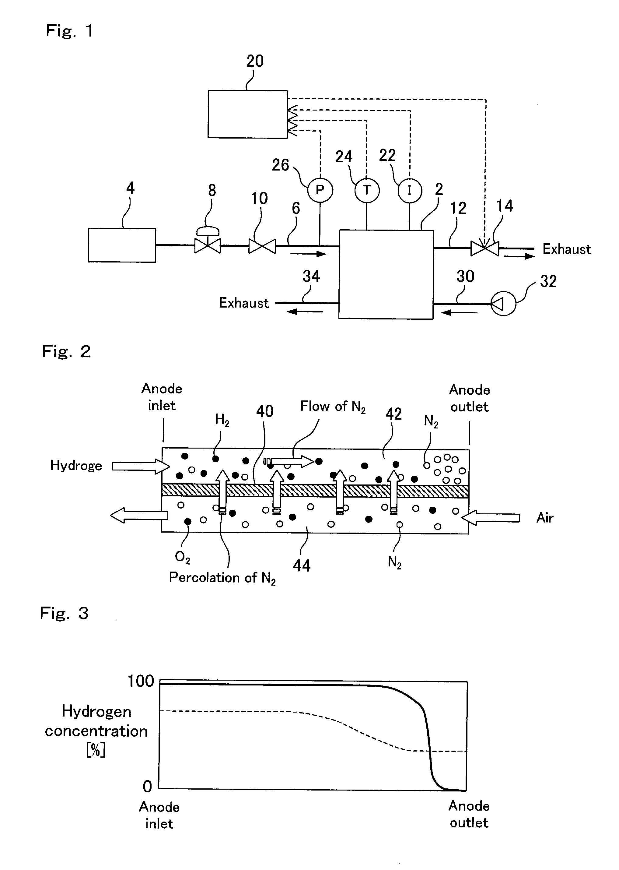
[0038]According to the fifth aspect of the present invention, since the predetermined load region for selecting the exhaust mode is set based on the gas temperature in the anode gas flow channel that relates to the
diffusion rate of the impurity in the anode gas flow channel,
discharge can be properly accomplished in the state where the impurity can be accumulated.
[0039]According to the sixth aspect of the present invention, since the predetermined load region for selecting the exhaust mode is set based on the
gas pressure in the anode gas flow channel that relates to the
diffusion rate of the impurity in the anode gas flow channel, discharge can be properly accomplished in the state where the impurity can be accumulated.
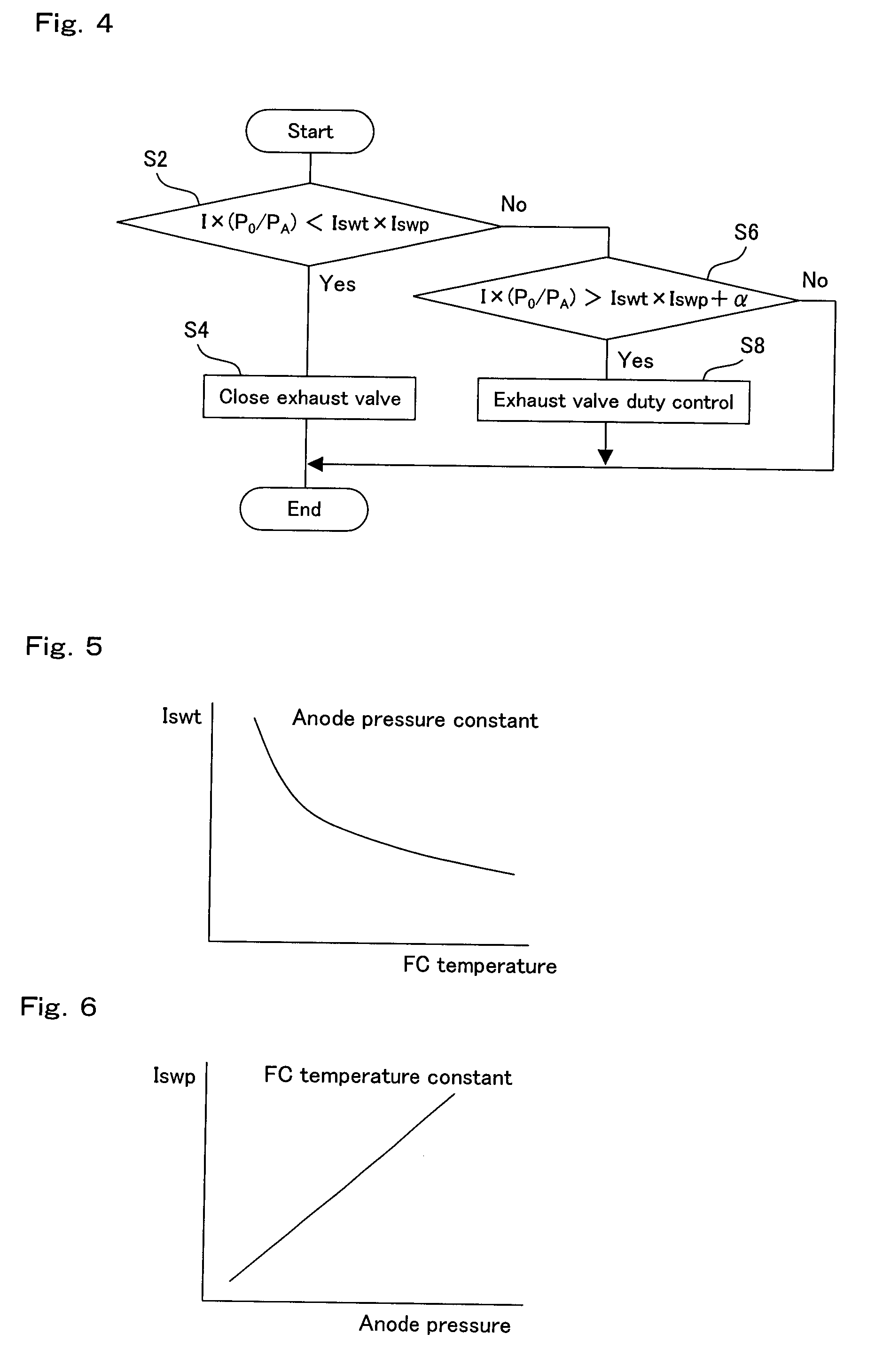
[0040]According to the seventh aspect of the present invention, when the exhaust mechanism operates in the exhaust mode to discharge a substantially smaller amount of gas than the consumption of the fuel gas in the anode gas flow channel to the outside of the system, the impurity accumulated at the downstream end of the anode gas flow channel can be discharged to the outside of the system in small amounts while reducing the amount of fuel gas wastefully discharged, and therefore, accumulation of the impurity that can cause degradation of the performance of the fuel cell can be prevented. When the exhaust mechanism operates in the closed mode to block communication between the anode gas flow channel and the outside of the system, wasteful discharge of the fuel gas in a condition where the impurity is not accumulated at the downstream end of the anode gas flow channel can be prevented. In addition, based on the comparison between the reference value calculated from the
physical quantity relating to the diffusion rate of the impurity in the anode gas flow channel and the comparison target value calculated from the physical quantity relating to the flow rate of the fuel gas in the anode gas flow channel, it can be properly determined whether or not the impurity can be accumulated at the downstream end of the anode gas flow channel. Therefore, a high level of prevention of degradation of the performance of the fuel cell and a high level of reduction of the amount of discharged fuel gas can be both achieved by switching between the exhaust mode and the closed mode based on the result of the comparison.
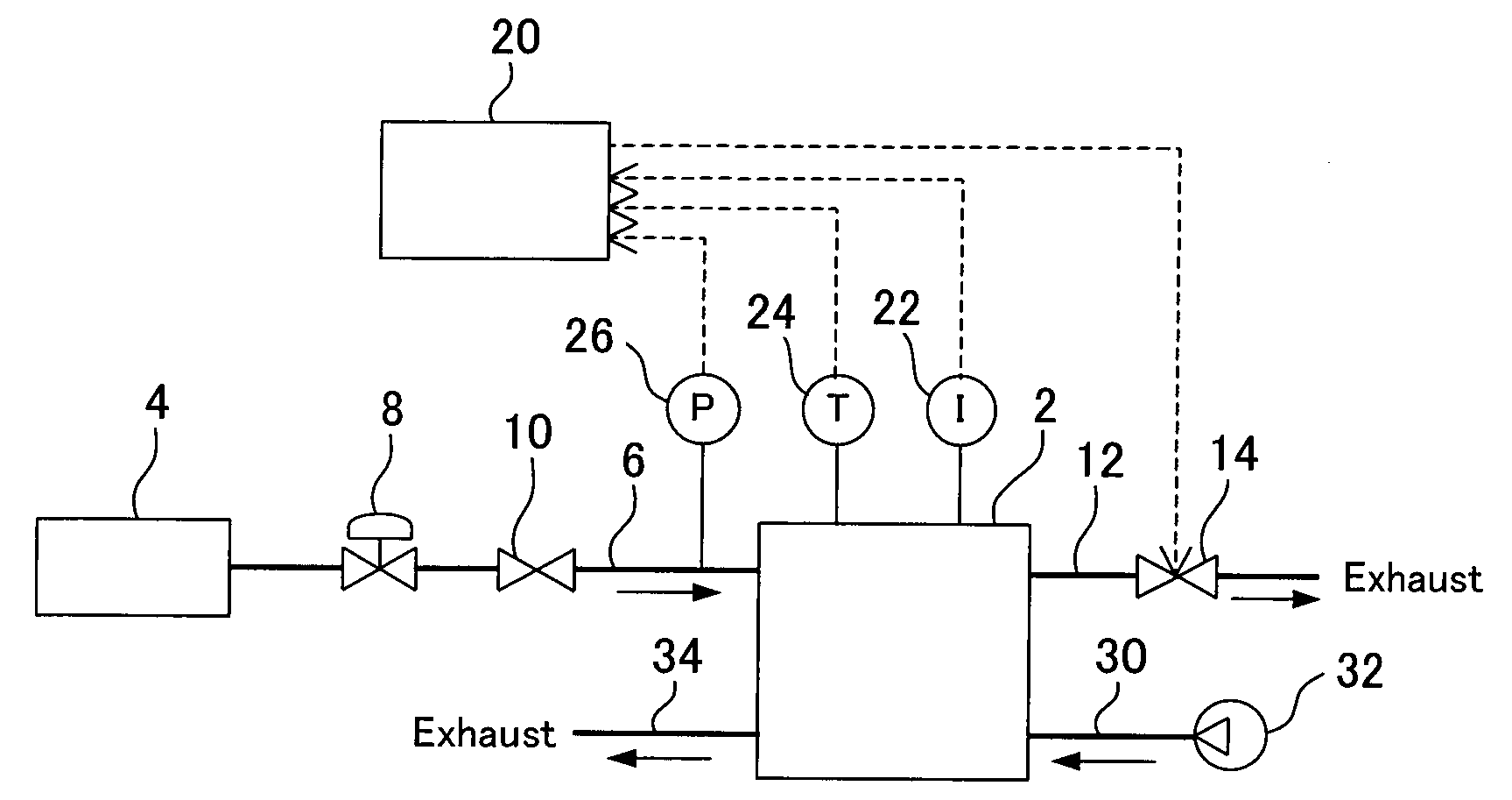
[0041]According to the eighth aspect of the present invention, since the current value of the fuel cell and the
gas pressure in the anode gas flow channel are measured, the flow rate of the fuel gas in the anode gas flow channel can be easily and accurately estimated. In addition, if the comparison target value described above is calculated based on the measurement values, it can be properly determined which of the exhaust mode and the closed mode is used.
[0042]According to the ninth aspect of the present invention, since the temperature of the fuel cell is measured, the diffusion rate of the impurity in the anode gas flow channel can be easily and accurately estimated. In addition, if the reference value described above is calculated based on the measurement value, it can be properly determined which of the exhaust mode and the closed mode is used.
[0043]According to the tenth aspect of the present invention, since the gas temperature in the anode gas flow channel is measured, the diffusion rate of the impurity in the anode gas flow channel can be easily and accurately estimated. In addition, if the reference value described above is calculated based on the measurement value, it can be properly determined which of the exhaust mode and the closed mode is used.
[0044]According to the eleventh aspect of the present invention, since the
gas pressure in the anode gas flow channel is measured, the diffusion rate of the impurity in the anode gas flow channel can be easily and accurately estimated. In addition, if the reference value described above is calculated based on the measurement value, it can be properly determined which of the exhaust mode and the closed mode is used.

