Cam lock burr hole plug for securing stimulation lead

Active Publication Date: 2010-01-28
BOSTON SCI NEUROMODULATION CORP
View PDF94 Cites 39 Cited by
  • Summary
  • Abstract
  • Description
  • Claims
  • Application Information

AI Technical Summary

Benefits of technology

[0024]The retainer further includes a retainer support, a slot formed in the retainer support for receiving the medical device (e.g., an open slot configured for laterally receiving the medical device), and a clamping mechanism having a movable clamping element and a cam configured for being rotated relative to the retainer support to linearly translate the movable clamping element towards the plug base, thereby laterally securing the retainer within the plug base. While the present inventions should not be so limited in their broadest aspects, the use of a cam provides a convenient, efficient, and robust means for securing the retainer to the plug base. In one embodiment, the retainer support includes a housing that contains the clamping mechanism. In this case, the retainer may further comprise a lid configured for being mounted to the housing to enclose the clamping mechanism. The housing may have a sidewall and an opening within the sidewall through which the movable clamping element is configured for linearly translating towards the plug base. In another embodiment, the plug base comprises an inner annular flange configured for engaging the movable clamping element when linearly translated through the opening within the sidewall, thereby axially securing the retainer wit

Problems solved by technology

Thus, lead displacements of less than a millimeter may have a deleterious effect on the patient's therapy.
Notably, any displacement of the portion of the lead exiting the burr hole will result in the translation of the electrodes positioned in the brain relative to the target site, thereby requiring the lead to be repositioned—a time consuming process.
For example, due mostly to their flexible nature and ability to lock in only one position, the clamping mechanisms of prior art burr hole plugs are not designed to firmly retain stimulation leads.
As such, the stimulation lead may still inadvertently move even when it is supposedly secured by the clamping mechanism.
If the diameter of the actual lead used with the burr hole plug is smaller than this intended diameter, the retention force applied to the lead by the clamping mechanism will not be sufficient.
In contrast, if the diameter

Method used


Image

  • Cam lock burr hole plug for securing stimulation lead
  • Cam lock burr hole plug for securing stimulation lead
  • Cam lock burr hole plug for securing stimulation lead

Examples


Embodiment Construction

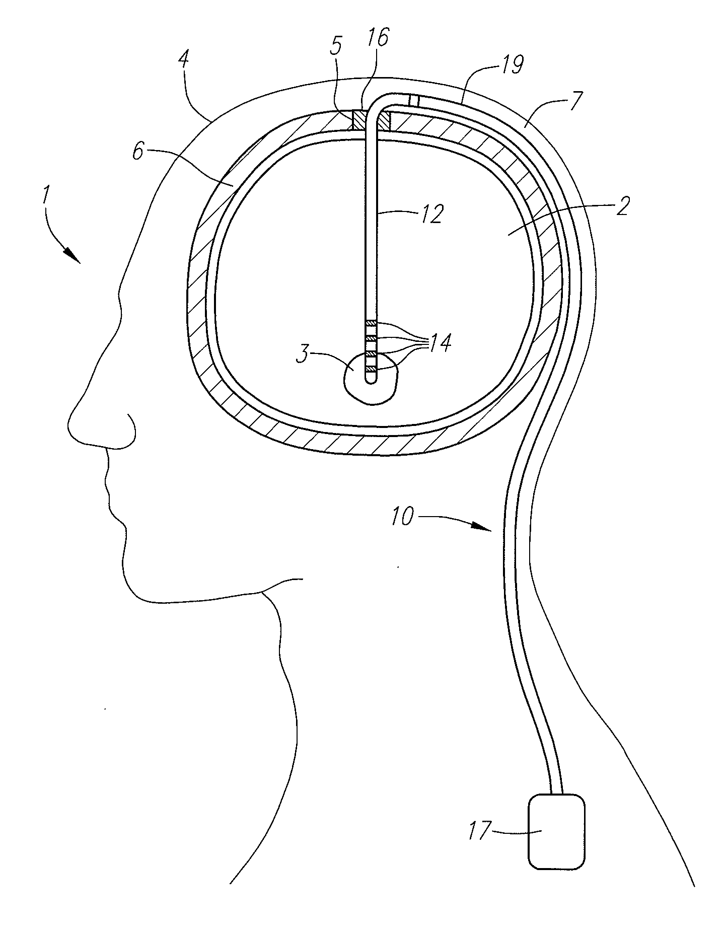
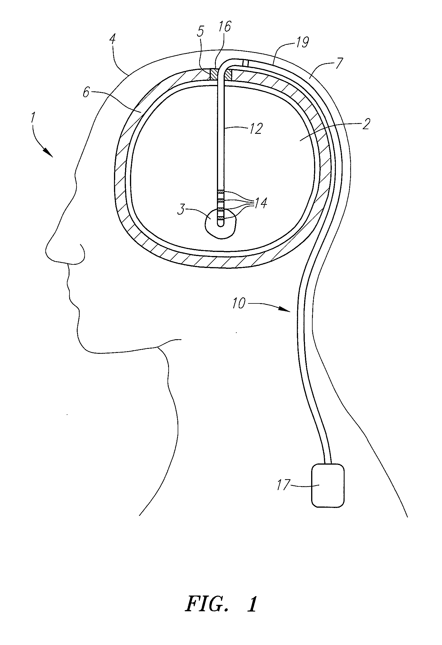
[0080]Turning first to FIG. 1, an exemplary DBS system 10 constructed in accordance with one embodiment of the present inventions is shown implanted within a patient for the treatment of a debilitating disease such as, Parkinson's disease, dystonia, essential tremor, seizure disorders, obesity, depression, etc. The system 10 comprises a stimulation lead 12 implanted within the parenchyma of the brain 2 of a patient 1 in order to position electrodes 14 carried by the distal end of the stimulation lead 12 adjacent a target tissue region 3, such as a deep brain structure of the patient (e.g., the ventrolateral thalamus, internal segment of globus pallidus, substantia nigra pars reticulate, subthalamic nucleus, or external segment of globus pallidus). Thus, electrical stimulation energy can be conveyed from the electrodes 14 to the target tissue region 3 to treat the disease. As can be seen, the stimulation lead 12 is introduced into the head 4 of the patient 1 via a burr hole 5 formed ...


PUM


Abstract

A burr hole plug comprises a plug base configured for being mounted around a cranial burr hole. The plug base includes an aperture through which an elongated medical device exiting the burr hole may pass. The burr hole plug further comprises a retainer configured for being mounted within the aperture of the plug base. The retainer includes a retainer support, a slot formed in the retainer support for receiving the medical device, and a clamping mechanism having a movable clamping element and a cam configured for being rotated relative to the retainer support to linearly translate the movable clamping element into the slot, thereby securing the medical device. The retainer further comprises another clamping mechanism having another movable clamping element and another cam configured for being rotated relative to the retainer support to linearly translate the other movable clamping element, thereby laterally securing the retainer within the plug base.

Description

RELATED APPLICATION[0001]This application is filed concurrently with U.S. patent application Ser. No. 12 / ______ (VIP Docket No. 08-00043-01), entitled “Cam Lock Burr Hole Plug for Securing Retainer / Plug Base”, the disclosure of which is expressly incorporated herein by reference.FIELD OF THE INVENTION[0002]The present inventions relate to apparatus for securing elongated medical devices, such as catheters or leads, within a cranial burr hole.BACKGROUND OF THE INVENTION[0003]Deep brain stimulation (DBS) and other related procedures involving implantation of electrical stimulation leads within the brain of a patient are increasingly used to treat disorders, such as Parkinson's disease, dystonia, essential tremor, seizure disorders, obesity, depression, restoration of motor control, and other debilitating diseases via electrical stimulation via stimulation of one or more target sites, including the ventrolateral thalamus, internal segment of globus pallidus, substantia nigra pars retic...

Claims


Application Information

Patent Timeline
IPC IPC(8): A61N1/04
CPCA61N1/0531A61F2/2875A61N1/0539A61N1/0534
Inventor BARKER, JOHN MICHAEL
Owner BOSTON SCI NEUROMODULATION CORP
Why Eureka
Try Eureka