

Apparatus to improve the efficiency of internal combustion engines, and method thereof
a technology of internal combustion engine and apparatus, which is applied in the direction of lift valve, valve details, output power, etc., can solve the problems of two-stroke engines, a large portion of the energy released in gasoline and diesel engines is lost, and the efficiency of the internal combustion engine is seldom above 22%,
- Summary
- Abstract
- Description
- Claims
- Application Information
AI Technical Summary
Benefits of technology
Problems solved by technology
Method used
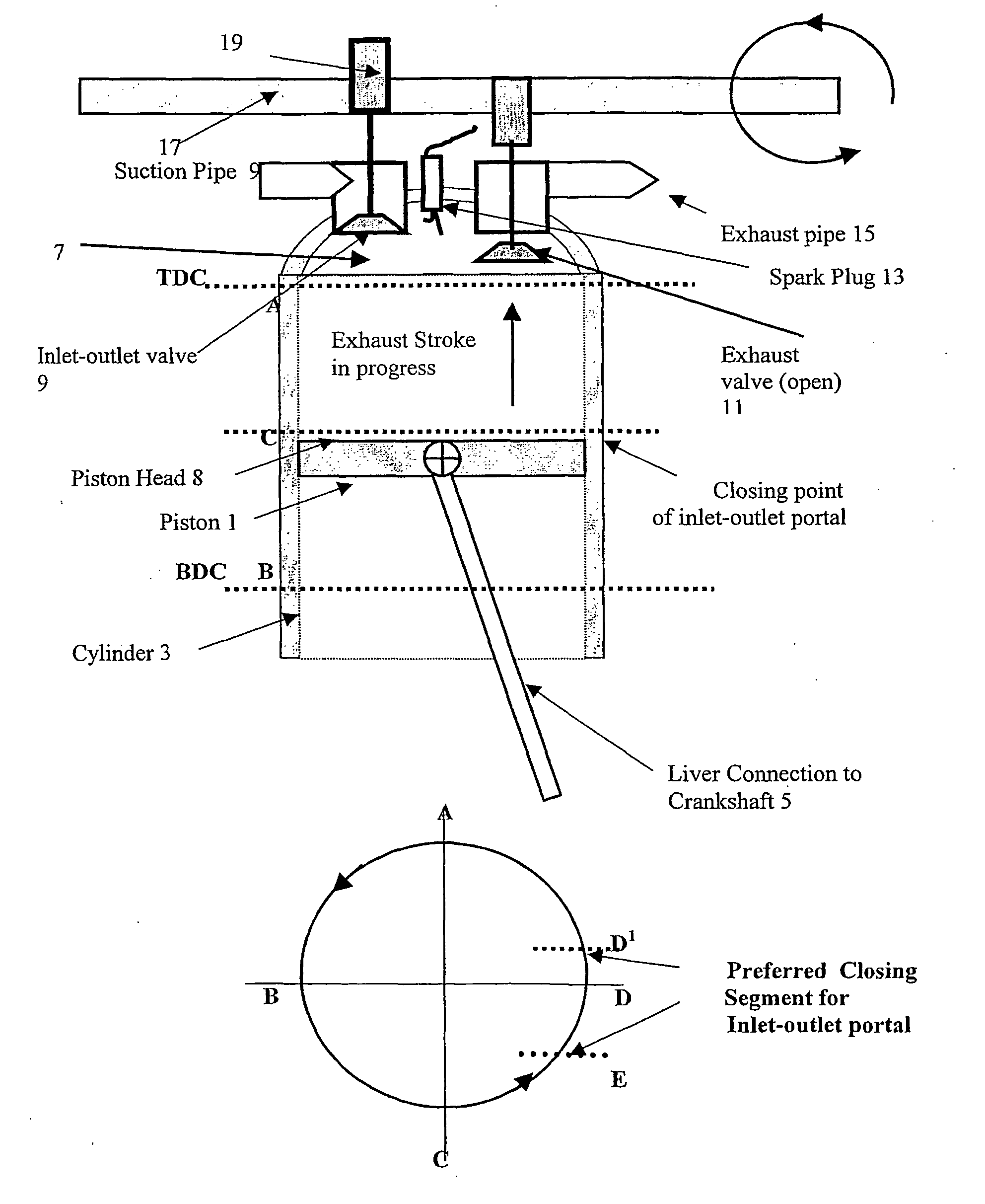
Image

Examples
example
[0420]Compare performance of a conventional engine operating on ‘Air Standard Otto Cycle’ and the same engine modified and being operated on the ‘Air Standard Atalla Modified Cycle’ as per the following:[0421]Assume a 4 stroke gasoline engine of 2000 cc size,[0422]Assume the engine is running at 2400 RPM[0423]Compression ratio 9.5[0424]Fuel supply 2720 Joule (650 cal) per litre,
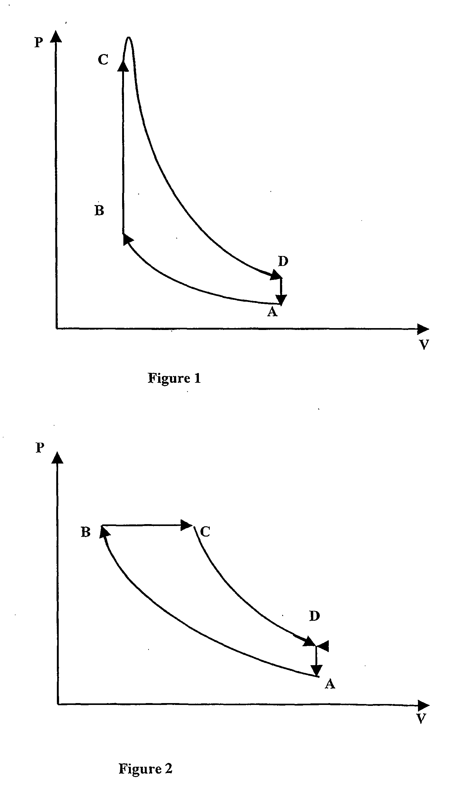
A—For Conventional Engines: ‘Air Standard Otto Cycle’
[0425]Assume the engine efficiency at 25%
Main Operation Indicators:
[0426]Releasedenergypersecond=2400 / 2*60s / min×2litres×2720=108800Joule / s
[0427]Where 2* represents the full 2 revolutions of the crank shaft to complete a full one power cycle,
Usefulenergypersecond=108800×25100=27200joule / sDevelophorsepower=2720010×1 / 75(kg / s)=36.26HP
[0428]Where 10 is the conversion factor between the thermal and mechanical energies.[0429]Kg.m=10 joule (2.39 cal)
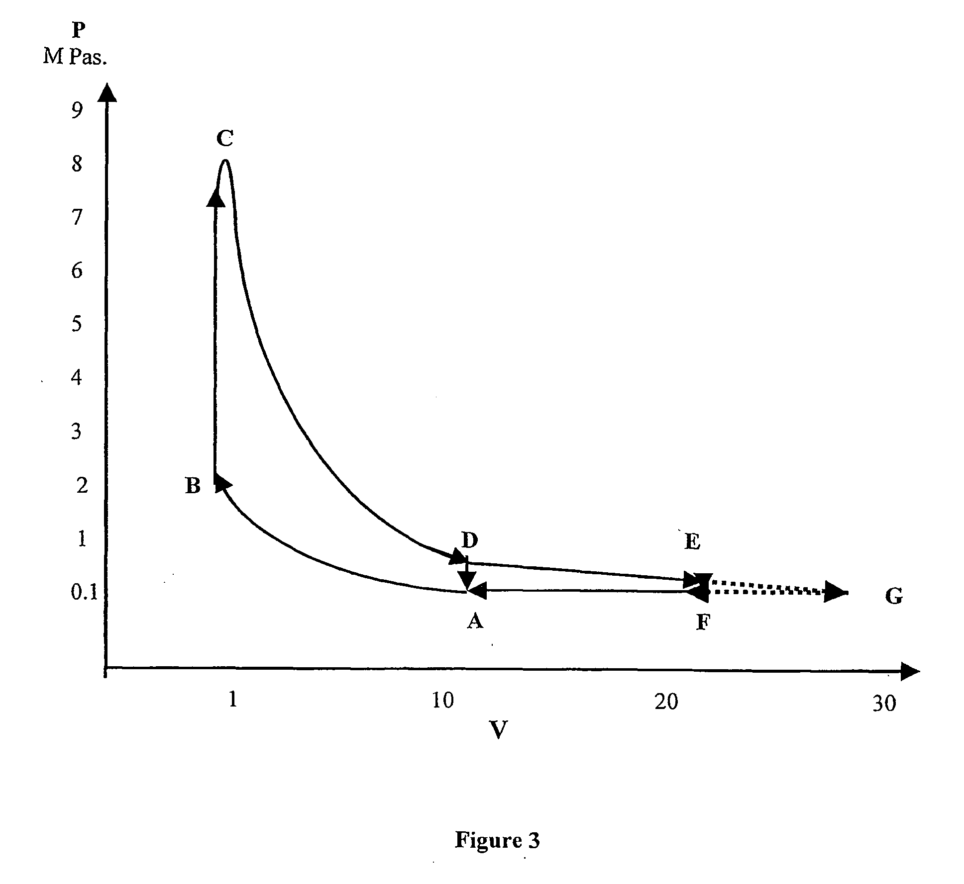
B—Engine with modifications: ‘Air Standard Atalla Modified Cycle’[0430]Same gasoline engine (active operation work wi...
PUM
 Abstract
Description
Claims
Application Information