Self-contained compression brakecontrol module for compression-release brakesystem of internal combustion engine

Active Publication Date: 2010-02-04
PACBRAKE
View PDF23 Cites 31 Cited by
  • Summary
  • Abstract
  • Description
  • Claims
  • Application Information

AI Technical Summary

Benefits of technology

[0019]Therefore, a compression-release brake system in accordance with the present invention with a self-contained compression brake control module improves and optimizes operational characteristics of the internal combustion e

Problems solved by technology

This creates a blow-down of the compressed cylinder gas and the energy used for compression is not reclaimed.
The result is engine braking, or retarding, power.
A conventional compression-release engine brake system has substantial cost associated with the hardware required to open the exhaust valve(s) against the extremely high load of a compressed cylinder charge.
Also, the sudden release of the highly compressed gas comes with a high level of noise.
In some areas, engine brake use is not permitted because the existing compression-release engine brake systems open the valves quickly at high

Method used


Image

  • Self-contained compression brakecontrol module for compression-release brakesystem of internal combustion engine
  • Self-contained compression brakecontrol module for compression-release brakesystem of internal combustion engine
  • Self-contained compression brakecontrol module for compression-release brakesystem of internal combustion engine

Examples


Embodiment Construction

[0036]The preferred embodiments of the present invention will now be described with the reference to accompanying drawings.

[0037]For purposes of the following description, certain terminology is used in the following description for convenience only and is not limiting. The words such as “front” and “rear”, “left” and “right”, “inwardly” and “outwardly” designate directions in the drawings to which reference is made. The words “smaller” and “larger” refer to relative size of elements of the apparatus of the present invention and designated portions thereof. The terminology includes the words specifically mentioned above, derivatives thereof and words of similar import.

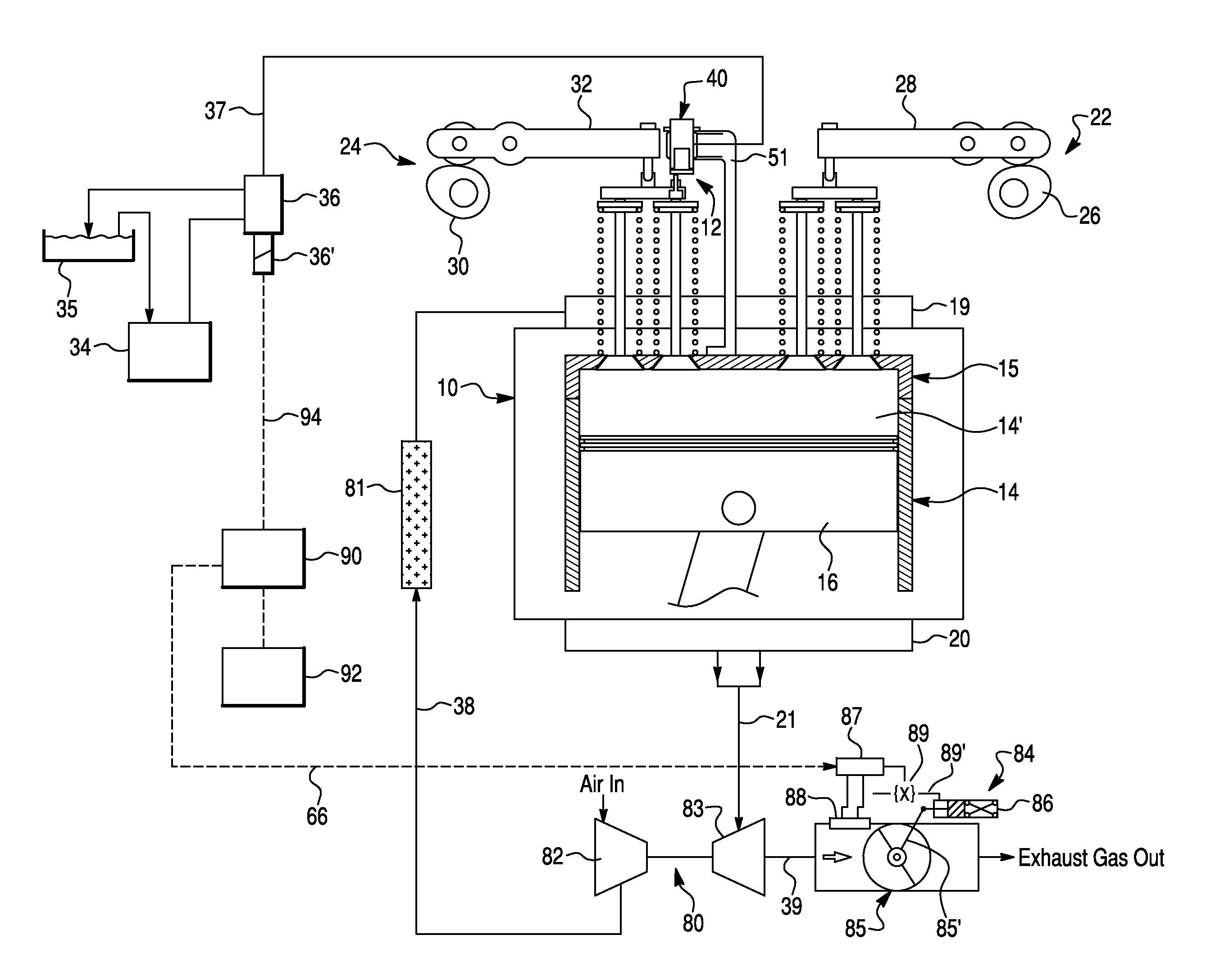
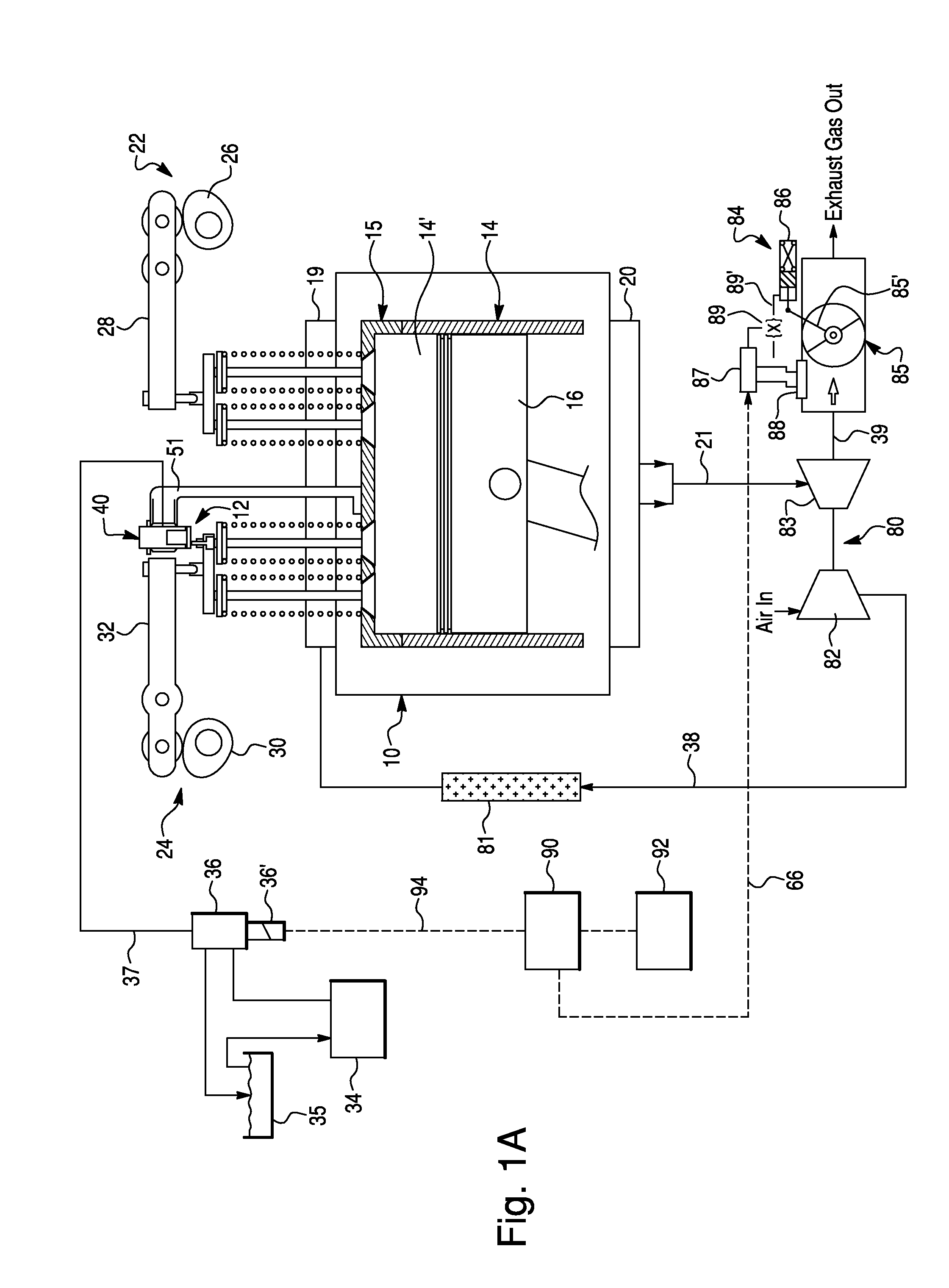
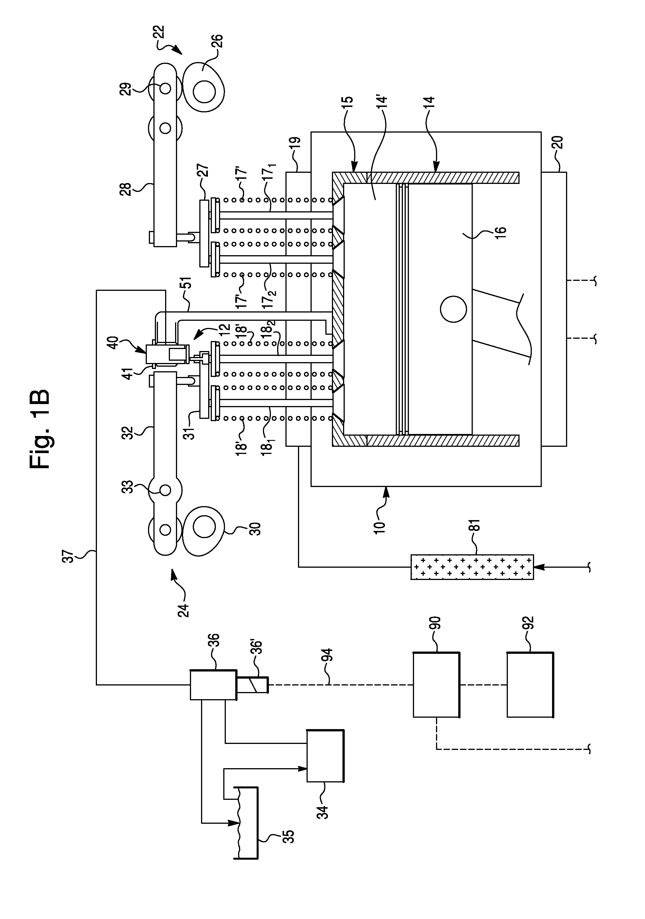
[0038]FIG. 1 schematically depicts a compression-release (or weeper) brake system 12 according to a first exemplary embodiment of the present invention, provided for an internal combustion (IC) engine 10. Preferably, the IC engine 10 is a four-stroke diesel engine, comprising a cylinder block 14 including a plurality o...


PUM


Abstract

A compression-release brake system for operating an exhaust valve of an engine during an engine braking operation. The compression-release brake system comprises a self-contained compression brake control module (CBCM) operatively coupled to the exhaust valve for controlling a lift and a phase angle thereof and a source of a pressurized hydraulic fluid. The CBCM includes a casing defining piston and actuator cavities, a slave piston mounted within the piston cavity, a check valve provided between a supply conduit and a slave piston chamber and a compression brake actuator disposed in the actuator cavity. The compression brake actuator includes an actuator element and a biasing spring. The actuator element selectively engages the check valve when deactivated so as to unlock the slave piston chamber, and disengages from the check valve when activated so as to lock the slave piston chamber. The actuator element is exposed to atmospheric pressure.

Description

CROSS-REFERENCE TO RELATED APPLICATION[0001]This Application claims the benefit under 35 U.S.C. 119(e) of U.S. Provisional Application No. 61 / 085,110 filed Jul. 31, 2008 by Meneely, V. et al.BACKGROUND OF THE INVENTION[0002]1. Field of the Invention[0003]The present invention relates to compression-release brake systems for internal combustion engines in general, and, more particularly, to a self-contained compression-release brake control module for a compression-release engine brake system of an internal combustion engine.[0004]2. Description of the Prior Art[0005]For internal combustion engines (IC engine), especially diesel engines of large trucks, engine braking is an important feature for enhanced vehicle safety. Consequently, the diesel engines in vehicles, particularly large trucks, are commonly equipped with compression-release engine brake systems (or compression-release retarders) for retarding the engine (thus, vehicle). The compression release engine braking provides si...

Claims


Application Information

Patent Timeline
IPC IPC(8): F02D9/06
CPCF01L13/065F02D9/06F02D13/04
Inventor MENEELY, VINCENTPRICE, ROBERT
Owner PACBRAKE
Why Eureka
Try Eureka