Electric propulsion system

a technology of electric propulsion and electric motor, which is applied in the field of electric propulsion systems, can solve the problems of reduced payload capacity, reduced interior space, and reduced performance of mild hybrid vehicles, and achieves enhanced acceleration, enhanced performance, and simplified feature modification of electric propulsion modules.

Inactive Publication Date: 2010-02-04
BLUWAV SYST LLC
View PDF0 Cites 268 Cited by
  • Summary
  • Abstract
  • Description
  • Claims
  • Application Information

AI Technical Summary

Benefits of technology

[0039]The invention provides an electric propulsion module and / or related components that allows vehicle platforms to be adapted by adding a variety of drive features with minimal modification of vehicle designs. For example, using one embodiment of the power module, a front-wheel drive vehicle can be upgraded to four-wheel drive with or without the hybrid features of regenerative braking, automatic engine shutdown and restart, and launch assist. In other examples, the added features could include any or all of the above hybrid features and / or active stability control (ASC), anti-lock braking (ABS), and active traction control (ATC). In another embodiment, an existing vehicle platform can be modified to provide all-electric propulsion.
[0040]An embodiment of the electric propulsion module defines an electric axle, complete with a mechanical drive system for two wheels, complete with a controller, power source, and energy storage. In some embodiments, the controller interfaces with an existing vehicle's data bus to obtain information such as steering input and speed of wheels other those connected to the power module drive system to enhance its provision of ASC, ABS, and ATC delivered through the direct control of the incorporated mechanical drive system.
[0043]The electric propulsion module is a particularly complementary combination with such a mild hybrid because the controls for starting and stopping the engine are already in place in the mild hybrid configuration. Thus, no additional modification of the controls is required to accommodate the upgrade. The addition of the electric propulsion module can boost the performance of the mild hybrid to that of a full hybrid vehicle, that is, one in which the power provided by the electric motor or independent in-wheel hub or body mounted motors is substantial in terms of power and work load. In addition, the features of regenerative braking, enhanced acceleration and other features can be added.
[0044]In a preferred embodiment, the electric propulsion module employs two motors. These may be hub motors or a pair of motors centrally mounted on a subframe and connected by half-shafts to the two wheels. The centrally-mounted motors may permit easier feature modification of the electric propulsion module since varied motor models may be substituted to match the desired performance specifications. Also, hub motors tend to have much higher mass, which may have adverse impact on performance and passenger comfort due to the concomitantly higher ratio of unsprung weight to sprung weight. Also, a sprung motor design may be cheaper than an electric propulsion module that employs hub motors.
[0045]In a variation on the foregoing embodiments, a clutch is provided between the rotors of two drive motors of the electric propulsion module. The clutch permits the rotors of the two drive motors to be selectively coupled. In a preferred embodiment, the coupling permits selective slipping or locking of the rotors (and consequently, the wheels). The clutch may be under automatic or drive control and may permit enhanced acceleration, enhanced performance under slippery conditions, or provide a mechanism to help a drive maintain or recover control during aggressive or emergency maneuvering. In a particular embodiments, two motors and the clutch are integrated in a common single housing.

Problems solved by technology

Therefore, such tear-ups may involve compromises that a vehicle manufacturer could not afford to make, such as reductions in payload capacity, interior space, seating, safety, and performance.
In addition, the economics of such modifications may involve the expense of substantial redesign to fit components and interface them mechanically and to permit optimal control.

Method used


Image

  • Electric propulsion system
  • Electric propulsion system
  • Electric propulsion system

Examples


Embodiment Construction

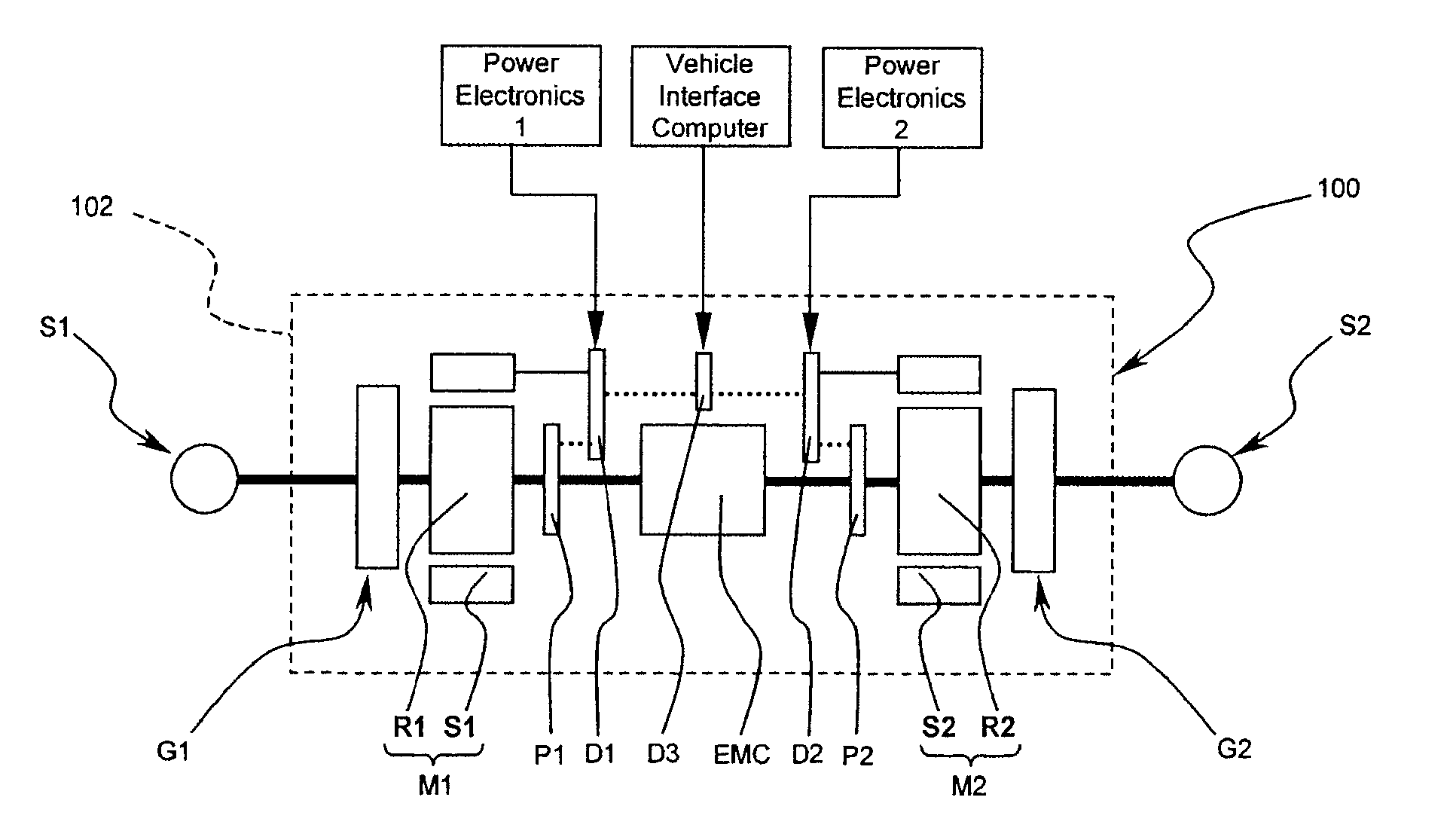
[0070]Referring now to FIG. 1, an electric propulsion axle 100 according to a preferred embodiment is disposed between first and second side shafts S1, S2, which rotationally couple the electric propulsion axle 100 to respective wheels (not shown in FIG. 1). Preferably, the first and second side shafts S1, S2 include so-called “half-shafts” or “side-shafts” that may include a relatively short driveshaft with either universal joints or constant velocity joints at either end of each drive shaft. In practice, the universal joints or constant velocity joints facilitate the transmission of torque via the driveshaft, regardless of the relative angular or vertical relationship of the driveshaft with respect to electric propulsion axle 100 or the corresponding wheel. Such an arrangement of the first and second side shafts S1, S2 allows movement in the suspension system that supports the wheel with respect to the vehicle, and simultaneously allows torque to be transmitted from the electric p...


PUM

PropertyMeasurementUnit
weightaaaaaaaaaa
currentaaaaaaaaaa
voltageaaaaaaaaaa

Abstract

The present invention relates to a motive power device for a vehicle, which is preferably retrofittable as front or rear axle. In a first embodiment, the device comprises a chassis (301) supporting at least one electric motor (318) and attached to the vehicle suspension fixtures with mounts (302, 304). Wheel hubs (377) are suspended from the chassis (301) and driven by the at least one motor (318). Further independent claims are included for a motive power device having a controller providing launch assist and / or stability control, a motive power device having at least two motors and a clutch therebetween, a vehicle provided with these various motive power devices, a method of making a vehicle, a clutch per se and an acceleration controller.

Description

PRIORITY DATA AND INCORPORATION BY REFERENCE [0001]This application claims priority to U.S. Provisional Patent Application Ser. No. 60 / 788,041 filed Apr. 3, 2006, and U.S. Provisional Patent Application Ser. No. 60 / 823,043 filed Aug. 21, 2006, which are incorporated herein by reference in their entirety.TECHNICAL FIELD [0002]An electrically powered system for propelling a vehicle is described. Particular features suited for a land vehicle that works as a hybrid propulsion system in concert with a combustion engine are described.BACKGROUND ART [0003]Many types of vehicles are known to be suitable for enhancing the ability to traverse land. Examples of known types of land vehicles include automobiles (e.g., cars, trucks, vans, snowmobiles, carts, and other types of vehicles) There are basic variations of vehicle architectures from the standpoint of their drive systems. Drive systems typically include rear-wheel drive, front-wheel drive, and four-wheel drive configurations. Conventiona...

Claims


Application Information

Patent Timeline
Patent Type & Authority Applications(United States)
IPC IPC(8): B60W10/06B60K1/00G06F19/00B60W10/04B60W20/00F16D27/02H05K13/00B60L50/16
CPCB60G3/20Y10T29/49002B60G2200/14B60G2200/144B60G2200/18B60G2202/12B60G2204/15B60G2204/20B60G2300/50B60K1/04B60K6/52B60K7/0007B60K17/043B60K17/356B60K2007/0046B60K2007/0061B60L2220/46B62D21/11F16D27/02F16D27/06F16D2027/002F16D2027/005Y02T10/6265B60L11/123B60L11/14Y02T10/7077Y02T10/6217Y02T10/648B60G11/15B60L50/61B60L50/16Y02T10/62Y02T10/70Y02T10/7072Y02T10/64
Inventor GLOCERI, GARY J.KENDALL, TODD A.ZHESHENG, LIDAWSON, MATTHEW J.ZHAO, ZILAI
Owner BLUWAV SYST LLC
Why Eureka
Try Eureka