Segmented optics circuit drive for closed loop fiber optic sensors

a closed-loop fiber optic sensor and segmented optics technology, applied in the field of gyro systems, can solve the problems of undesirable deadband errors, significant convergence of loop errors, and limited resolution metrics of these sensors, and achieve the effect of improving the output resolution of an optical drive componen

Active Publication Date: 2010-02-04
HONEYWELL INT INC
View PDF12 Cites 4 Cited by
  • Summary
  • Abstract
  • Description
  • Claims
  • Application Information

AI Technical Summary

Benefits of technology

[0015]As will be readily appreciated from the foregoing summary, the invention provides means for improving the output resolution of an optical drive component in an optical sensor.

Problems solved by technology

This truncation can also introduce an asymmetry that, in the presence of vibration, could rectify into rate error.
Additionally, loop error may take a significant amount of time to converge to the appropriate phase shift, and this time for convergence may be further extended with the truncation of signals supplied to the DAC.
The resolution metrics of these sensors are substantially limited by the data truncation associated with the use of only one high resolution DAC in the IOC drive component of the sensors.
In high precision applications, these truncated signals can cause undesirable deadband errors.
Even though over a long period of time the closed-loop architecture maintains a bias error which averages to zero, quantization error remains in terms of angle white noise.
Unfortunately, these high resolution converters are expensive and still require truncation well below 23-bit resolution.
Unfortunately, such techniques invariably inject certain unwanted noise into the converter component.
This unwanted noise can lead to inconsistent sensor output and decreased system throughput.

Method used


Image

  • Segmented optics circuit drive for closed loop fiber optic sensors
  • Segmented optics circuit drive for closed loop fiber optic sensors
  • Segmented optics circuit drive for closed loop fiber optic sensors

Examples


Embodiment Construction

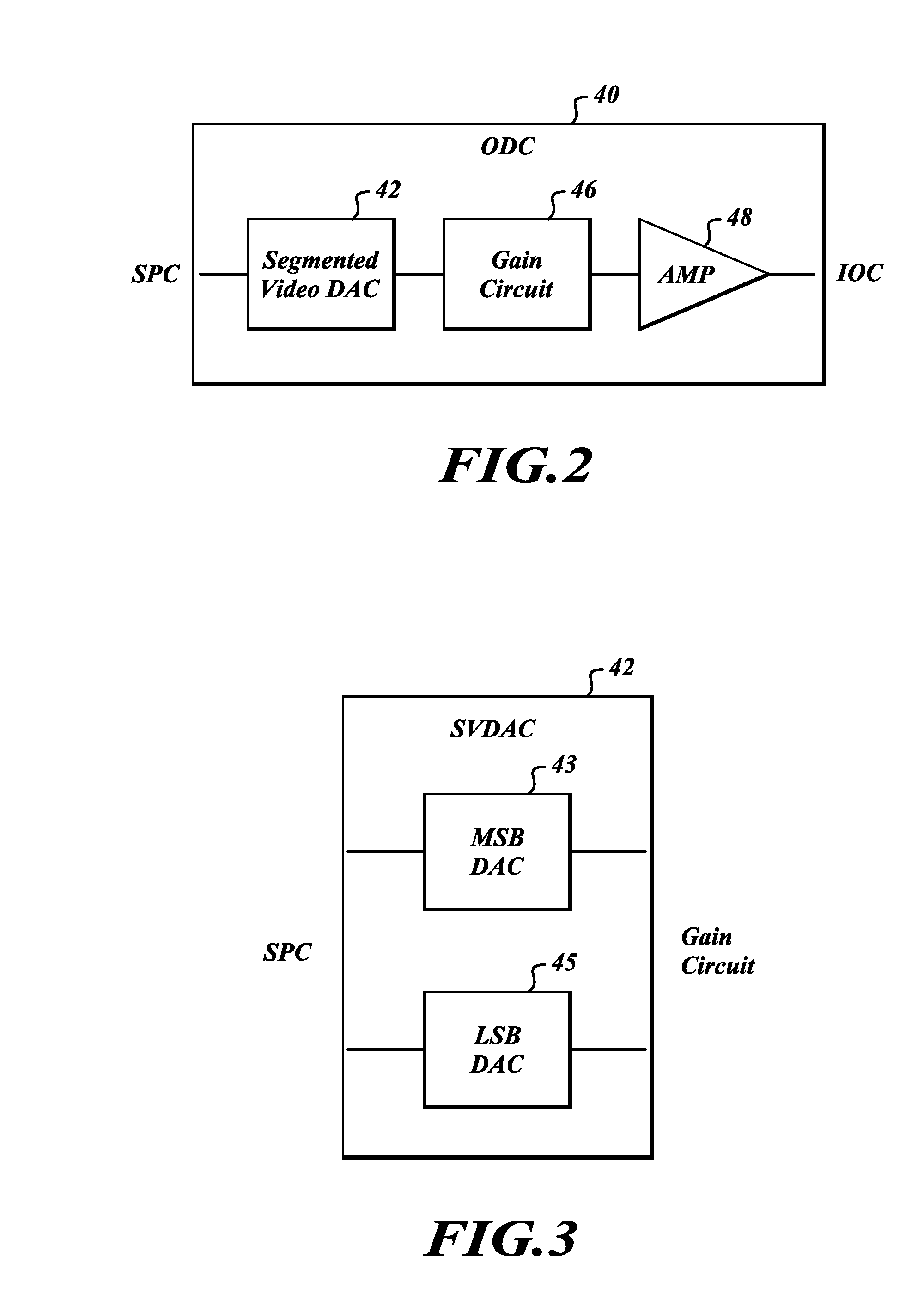
[0022]The present invention relates to a system and method for improving the output resolution of an optical drive circuit in an optical sensor device. In accordance with at least one embodiment, the output bit resolution of an optical drive circuit can be significantly increased by segmenting data conversion between two distinct converter components in the optical drive circuit.

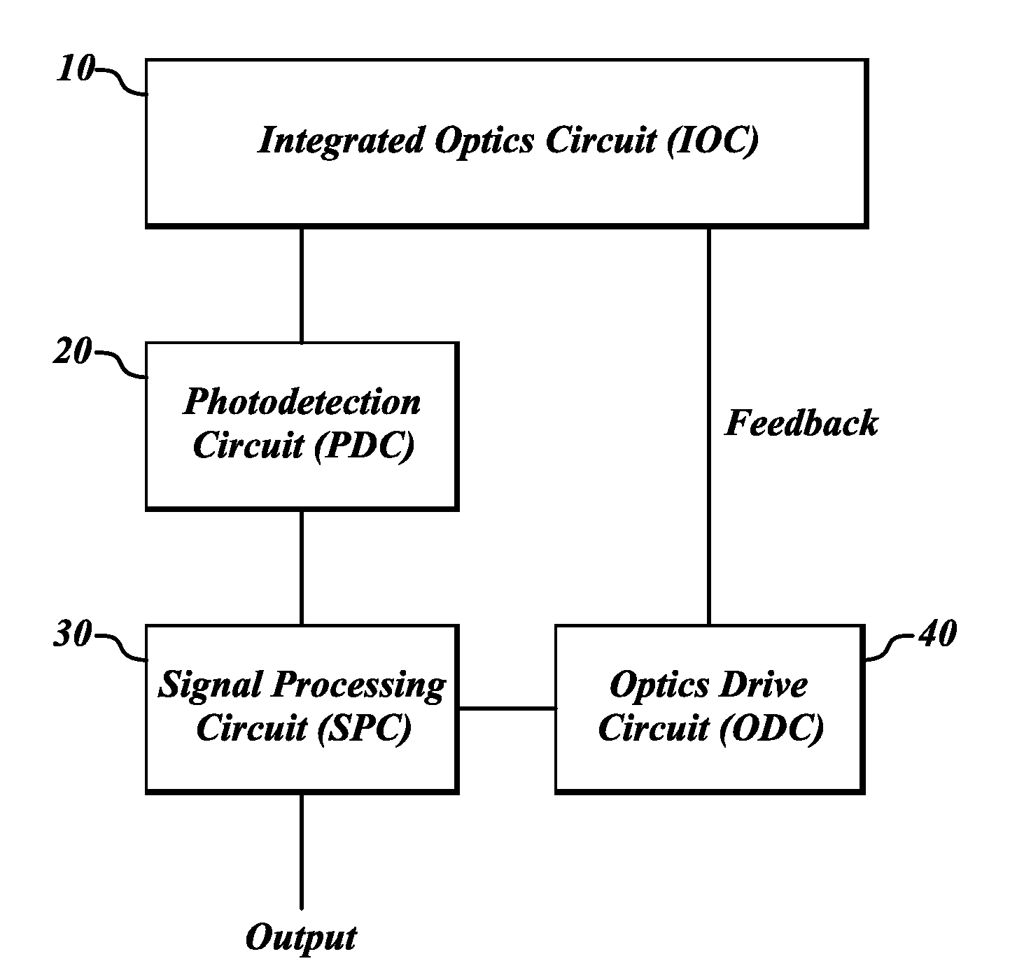
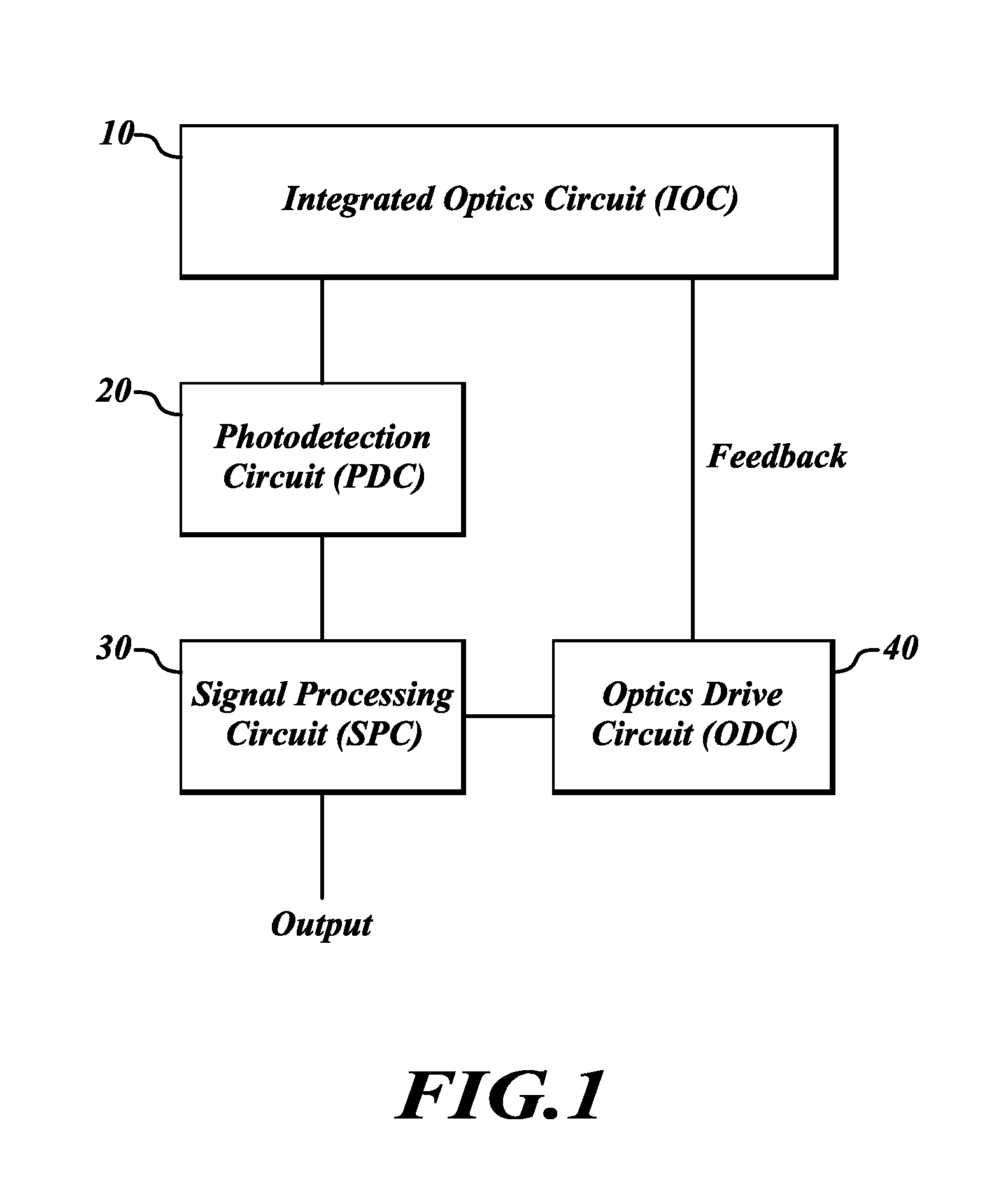
[0023]FIG. 1 illustrates a closed-loop architecture of an optical sensor 8 formed in accordance with an embodiment of the present invention. The closed-loop sensor 8 includes an integrated optics circuit (IOC) 10, a photodetection circuit (PDC) 20, a signal processing circuit (SPC) 30, and an optics drive circuit (ODC) 40. The closed loop optical sensor 8 may be one of any number of different types of closed-loop sensors, for example, closed-loop fiber optic sensors and gyros.

[0024]When the optical sensor 8 is implemented as a closed-loop fiber optic gyro, the sensor 8 measures an angular velocity or a veloc...


PUM


Abstract

Systems and methods for improving output resolution of an optical drive circuit in an optical sensor. The optical sensor circuit includes an optics circuit that generates analog measurement data, a detector circuit that detects the analog measurement data and converts the analog measurement data to a digital measurement data, and a signal processing circuit that demodulates the digital measurement data and generates a segmented digital signal based on the demodulated digital measurement data. The optical sensor circuit further includes an optics drive circuit that generates an analog drive signal based on the segmented digital signal. The analog drive signal is then used to drive the optical circuit.

Description

FIELD OF THE INVENTION[0001]The present invention generally relates to gyro systems, and more particularly to modulating optical signals in interferometric fiber optic gyros (IFOGs).BACKGROUND OF THE INVENTION[0002]Gyros have been used to measure rotation rates or changes in angular velocity about an axis of rotation. A basic conventional fiber optic gyro (FOG) includes a light source, a beam generating device, and a coil of optical fiber coupled to the beam generating device that encircles an area about a sensing axis. The beam generating device transmits light beams into the coil that propagate in a clockwise (CW) direction and a counter-clockwise (CCW) direction along the core of the optical fiber and both ultimately impinge on a photodetector (e.g., a photodiode electrically coupled to a photodetection system). Many FOGs utilize glass-based optical fibers that conduct light along a solid glass core of the fiber. The two counter-propagating (e.g., CW and CCW) beams experience dif...

Claims


Application Information

Patent Timeline
Patent Type & Authority Applications(United States)
IPC IPC(8): H03M1/00
CPCH03M1/68G01C19/726
Inventor KEITH, GREGG
Owner HONEYWELL INT INC
Why Eureka
Try Eureka