Retardation compensation element, van liquid crystal display device, and liquid crystal projector

a technology of display device and display element, which is applied in the direction of projectors, optics, instruments, etc., can solve the problems of poor alignment of liquid crystal molecules, lowering contrast, and tone reversal to reverse the brightness of neutral colors, so as to improve contrast and extend viewing angl

Inactive Publication Date: 2010-02-04
FUJIFILM CORP
View PDF9 Cites 21 Cited by
  • Summary
  • Abstract
  • Description
  • Claims
  • Application Information

AI Technical Summary

Benefits of technology

[0025]According to the present invention, the biaxial birefringent medium of the retardation compensation element compensates the phase difference due to the pre-tilt of the liquid crystal molecules in the VAN-LCDs as well as the phase difference of the incident light on the liquid crystal layer. Accordingly, the contrast is improved in the VAN-LCDs, and the viewing angle thereof is extended.

Problems solved by technology

However, while it provides good contrast when viewed from the front, the VAN-LCD, similar to the other operation modes, hardly keeps good display performance when viewed from an oblique angle, and results in lowering the contrast or causing tone reversal to reverse the brightness of neutral colors.
These drawbacks are due partly to the obliquely incident light on the liquid crystal layer.
If the liquid crystal layer is driven as a densely-arranged pixel array using a micro-electrode structure, a lateral electric field generated when a voltage is applied to the pixels next to the voltage-off pixels produces reverse tilt domains where the liquid crystal molecules for the voltage-off pixels are aligned opposite to an intended direction, and causes poor alignment of the liquid crystal molecules.
However, the C-plate is not able to compensate the phase difference caused by the birefringence due to the pre-tilt of the liquid crystal molecules.
When the C-plate and the A-plate are to be used together, on the other hand, there are not only few choices in material but there is actually no material to provide a high level of durability and mass productivity.
For example, while the A-plate is generally composed of a uniaxially-stretched polymer film or a birefringent retardation plate made by a microfabrication technique, the polymer film is not very durable and the birefringent retardation plate is not suitable for mass production.
Accordingly, it is difficult for the C and A-plates combination to improve the contrast of the VAN-LCD while extending the viewing angle.
Still further, when two O-plates are layered with their fast axes orthogonal to each other, this O-plate pair is isotropic to the light moving in a normal line direction to the surface, and hardly compensates the phase difference of the light passing vertically through the VAN-LCD.
In other words, these O-plates cannot compensate the phase difference due to the pre-tilt of the liquid crystal molecules.
Accordingly, the disclosure of this patent document may not easily applied to the VAN-LCDs.

Method used


Image

  • Retardation compensation element, van liquid crystal display device, and liquid crystal projector
  • Retardation compensation element, van liquid crystal display device, and liquid crystal projector
  • Retardation compensation element, van liquid crystal display device, and liquid crystal projector

Examples


first embodiment

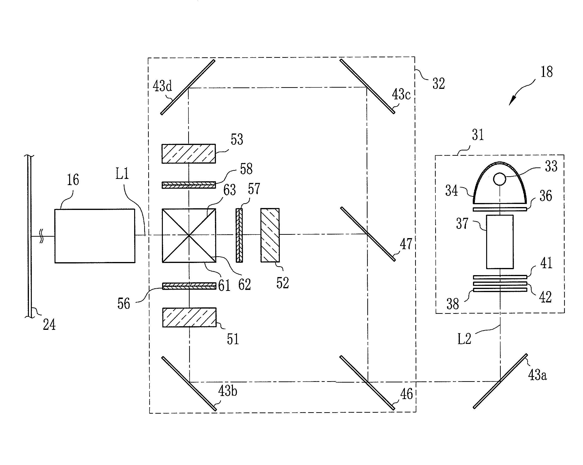
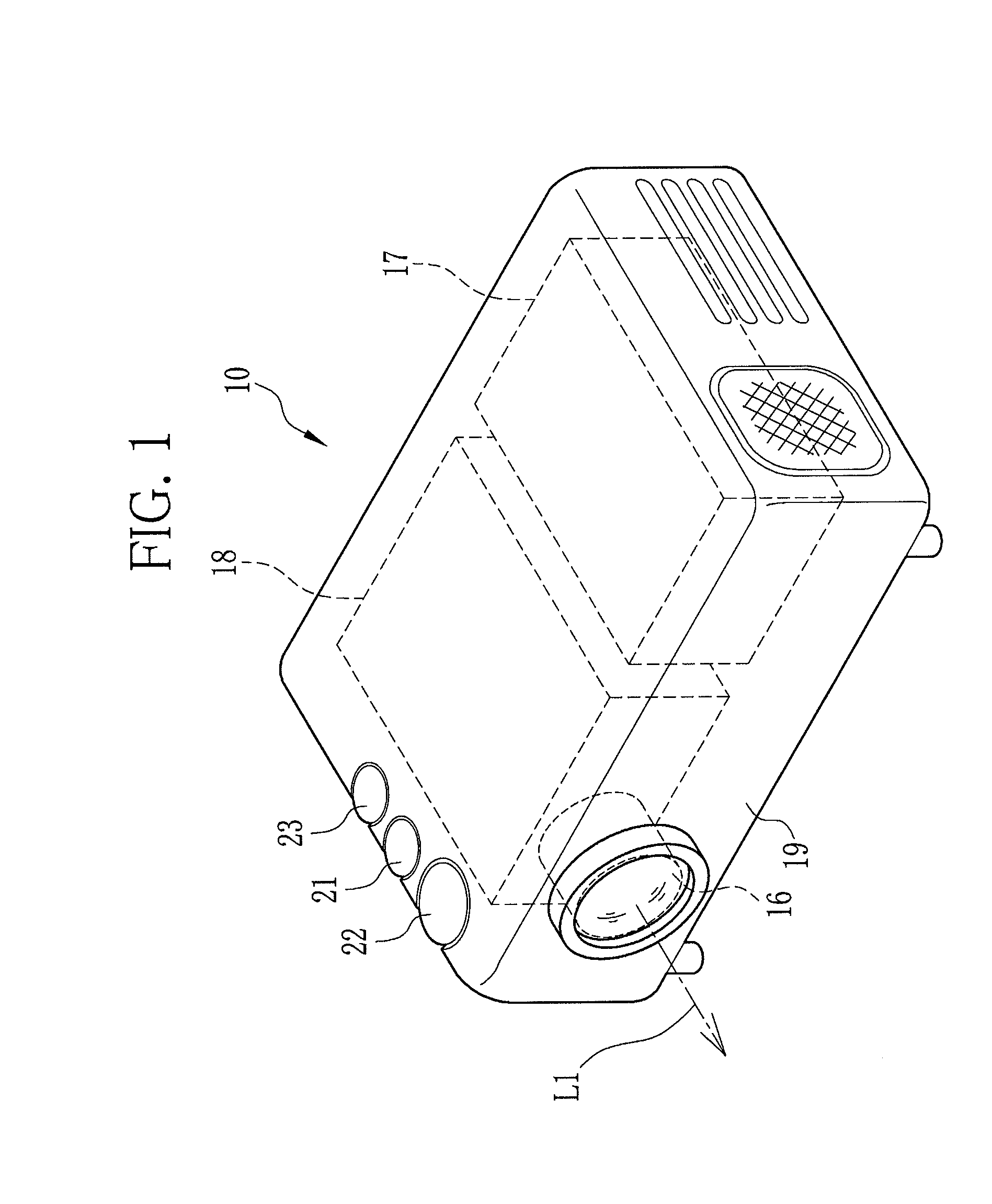
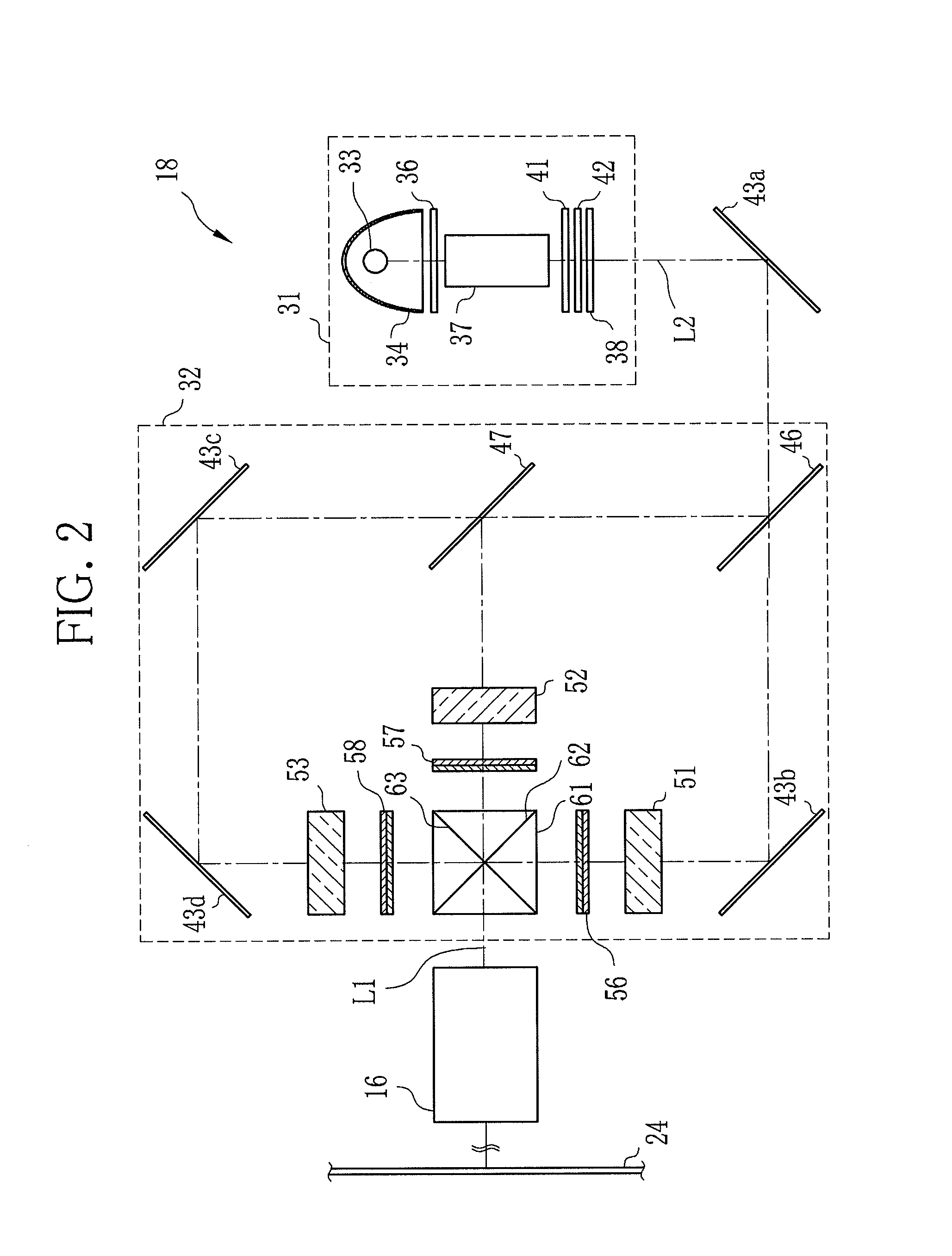
[0037]Referring to FIG. 1, a projector 10 that uses a phase difference compensation film according to the present invention includes a projection lens 16, a projector driver 17 and a display optical system 18.

[0038]The projector 10 also has a zooming dial 21, a focusing dial 22 and a light amount adjuster dial 23 on a top surface of a housing 19. On a rear surface of the housing 19, one or more connection terminals (not shown) are provided for connection to computers and other external devices.

[0039]The projection lens 16 enlarges projection light coming from the display optical system 18, and projects it onto a screen 24 (see, FIG. 2). The projection lens 16 is composed of, for example, a zooming lens, a focusing lens and an aperture stop. The zooming lens and the focusing lens are movable along an axis of the projection light (projection light axis) L1. Following the operation of the zooming dial 21, the zooming lens moves to adjust the magnification of a projected image. The focu...

example 1

[0102]A liquid crystal display device was prepared to have retardation Rth (in the thickness direction of the liquid crystal layer) of +400 nm and the liquid crystal molecules with a pre-tilt angle of 85 degrees. A retardation compensation element was then prepared from an O-plate with retardation of +8 nm and an inclination angleφ of the largest principal refractive index n1 of 20.5 degrees, and a C-plate with retardation Rth in the thickness direction of −400 nm. These liquid crystal display device and retardation compensation element were combined to compose a projector, and a conoscopic figure of the liquid crystal display device was measured to evaluate the contrast of the liquid crystal display device and the projector. The conoscopic figure was measured within the ranges of −30≦θ≦+30 and 0≦φ≦360 around a central point on a normal line to the liquid crystal display device, wherein φ represents an angle of rotation around the central point and θ represents an angle of measureme...

second embodiment

[0108]Referring to FIG. 10, a retardation compensation element 110 includes a first O-plate 111, a second O-plate 112 and the C-plate 86. The first and the second O-plates 111, 112 are fabricated in the same manner and have the same optical property as the O-plate 85 of the first embodiment, and thus the same elements are designated by the same reference numerals as the O-plate 85. Also, the same liquid crystal display device is used in this embodiment, and thus the same components as the first embodiment are designated by the same reference numerals.

[0109]The retardation compensation element 110 is different from the retardation compensation element 56 in the arrangement of the O-plate with respect to the liquid crystal layer. Specifically, as shown in FIG. 10 and FIG. 11, the first and the second O-plates 111, 112 are arranged to form an angle δ of substantially 90 degrees between a fast axis L9 of the first O-plate 111 and a fast axis L10 of the second O-plate 112. Additionally, ...


PUM

PropertyMeasurementUnit
angleaaaaaaaaaa
angleaaaaaaaaaa
tilt angleaaaaaaaaaa

Abstract

A retardation compensation element (56) is composed of a C-plate (86) and an O-plate (85). The O-plate (85) is a biaxial birefringent medium made of an obliquely deposited organic material, and has a fast axis (L6) parallel to the orthographic projection of a deposition direction (96) onto the surface of the O-plate (85). Between a liquid crystal display device (51) and an analyzer (68), the O-plate (85) is arranged such that the fast axis (L6) and a tilt direction (L8) of liquid crystal molecules (75) parallel to each other, and that the deposition direction (96) and the tilt direction (L8) face the opposite direction. The C-plate (86) is disposed above the O-plate (85) between the liquid crystal display device (51) and the analyzer (68).

Description

TECHNICAL FIELD[0001]The present invention relates to a retardation compensation element combined with liquid crystal devices so as to compensate a phase difference of light passing through the liquid crystal device, and more particularly to a retardation compensation element to compensate a phase difference of light passing through a VAN liquid crystal device in which liquid crystal molecules are vertically aligned when no voltage is applied.BACKGROUND ART[0002]A liquid crystal display device (hereinafter, LCD) can be found in a variety of electronic hardware, such as a display of calculators, electronic dictionaries, televisions and digital cameras, a monitor of car navigation system, cellular phones and computers, and a display panel of projectors.[0003]According to the operation modes of a liquid crystal layer, the LCD can be classified into several types, such as TN (Twisted Nematic) LCD, VAN (Vertical Alignment Nematic) LCD, IPS (In-Plane Switching) LCD and OCB (Optically Comp...

Claims


Application Information

Patent Timeline
Patent Type & Authority Applications(United States)
IPC IPC(8): G02F1/13363G02F1/1335
CPCG02B5/3083G02F1/133634G03B33/12G03B21/14G02F1/1393G03B21/2073G03B21/208
Inventor NAKAGAWA, KENICHITAKAHASHI, HIROKI
Owner FUJIFILM CORP
Why Eureka
Try Eureka