Pileup rejection in an energy-dispersive radiation spectrometry system

a radiation spectrometry and energy-dispersive technology, applied in the direction of optical radiation measurement, pulse characteristics measurement, instruments, etc., can solve the problems of pile up rejection, rise time, and step in the preamplifier output that is not instantaneous, and achieve the effect of full efficiency

Active Publication Date: 2010-02-04
JUDITH B MOTT REVOCABLE TRUST DATED JUNE 6 2006 AS AMENDED & RESTATED
View PDF52 Cites 25 Cited by
  • Summary
  • Abstract
  • Description
  • Claims
  • Application Information

AI Technical Summary

Benefits of technology

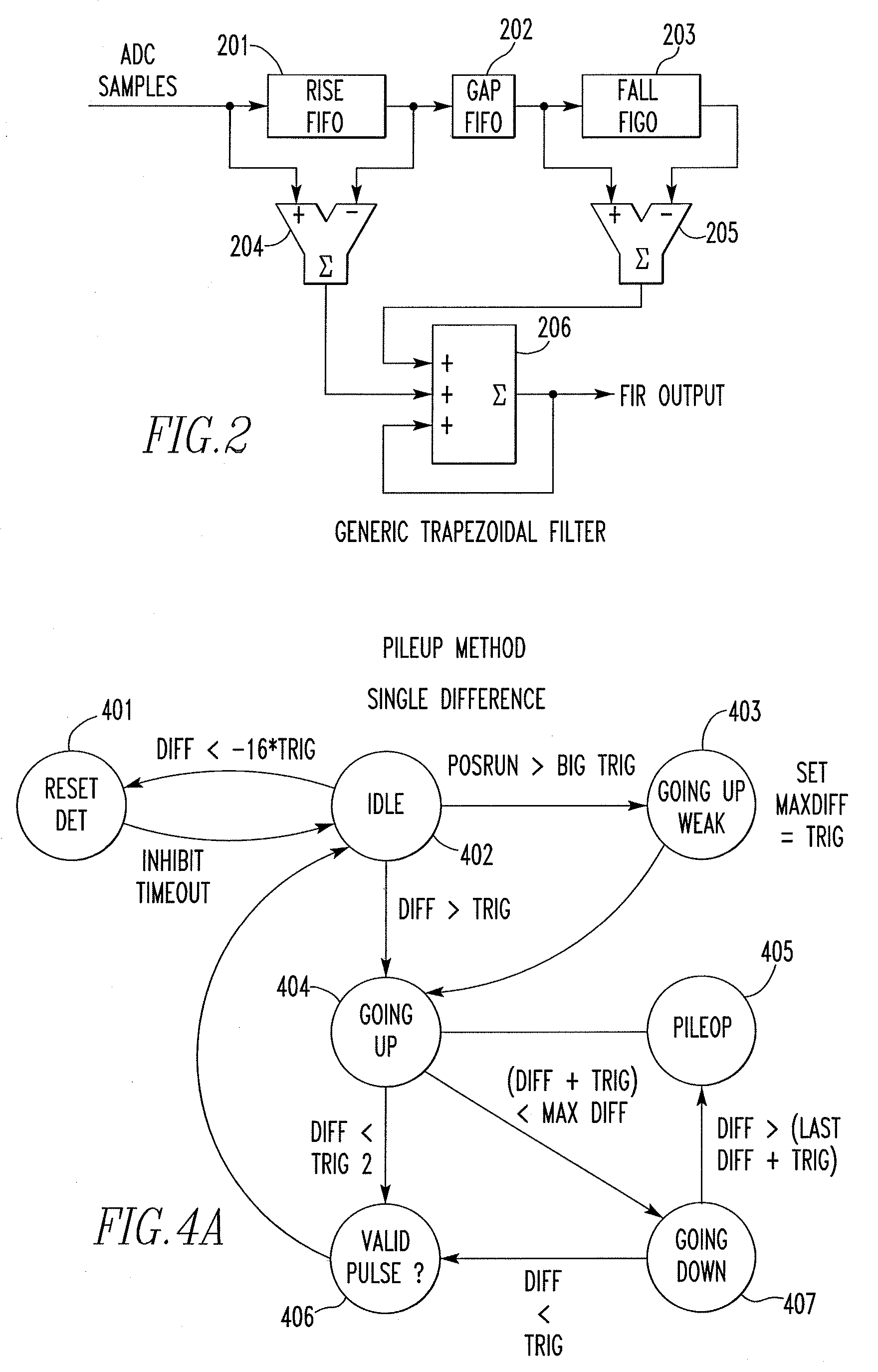
[0021]In one embodiment, a method of detecting a pileup from an output signal of a preamplifier of an energy-dispersive radiation spectrometry system, such as an X-ray spectrometry system or a gamma-ray spectrometry system, wherein a filter of the energy-dispersive radiation spectrometry system generates a first pulse in response to the output signal, and wherein the energy-dispersive radiation spectrometry system has one or more fast channels having an energy of full efficiency wherein substantially all photons received by the energy-dispersive radiation spectrometry system having at least the energy of full efficiency are detected. The method includes measuring an above threshold time duration which is a time during which the first pulse is above a minimum detectable threshold energy of

Problems solved by technology

Second, the steps in the preamplifier output are not instantaneous.
This is due to bandwidth limitations, device capacitance, and the time required for all the electrons generated by an X-ray to reach the anode of the sensor.
As a result, the electron cloud collection time is approximately constant, and the “rise time” of the preamplifier signal (the width of the sigmoidal step) is dominated by bandwidth limitations due to the relatively large capacitance of the device.
Thus, pulse processors need to be able to effectively detect the occurrence of pile up, which when detected, will result in the energy measurements associated therewith being discarded (referred to as pile up rejection).
In other words, it is much more difficult to detect near coincidences between small (low energy) pulses than large ones.
Because

Method used


Image

  • Pileup rejection in an energy-dispersive radiation spectrometry system
  • Pileup rejection in an energy-dispersive radiation spectrometry system
  • Pileup rejection in an energy-dispersive radiation spectrometry system

Examples


Embodiment Construction

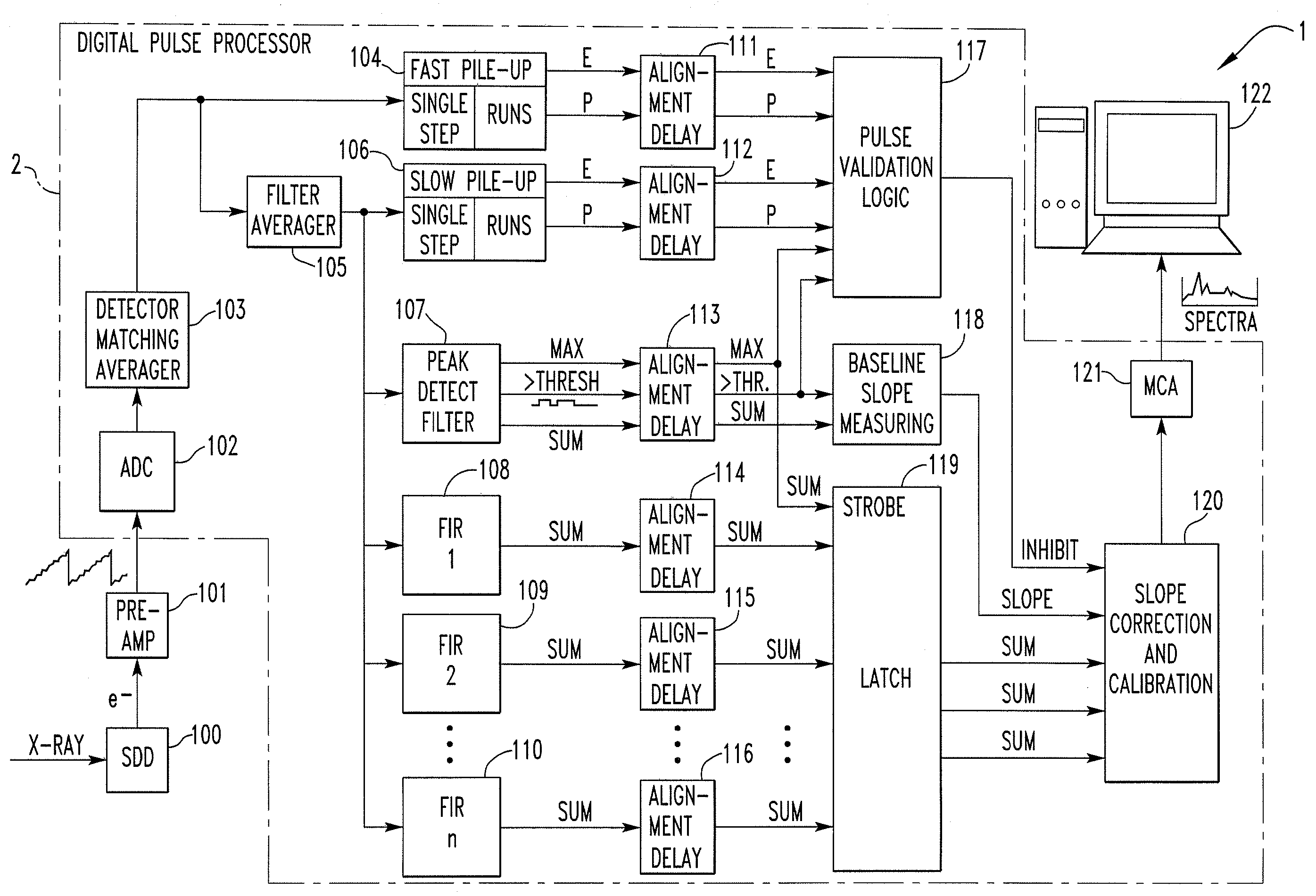
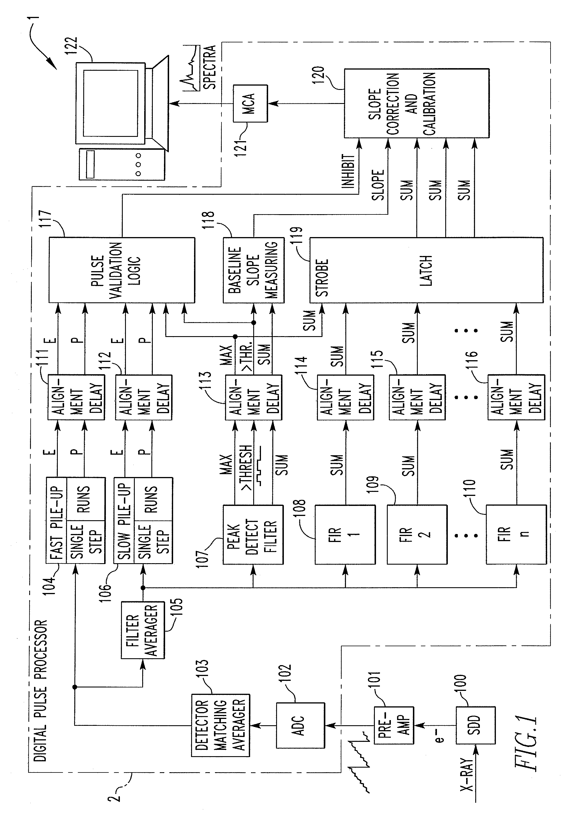
[0034]As noted in the Background of the Invention, the subject matter described herein applies to both tail pulse and pulsed reset preamplifiers. However, for ease of illustration and description, invention will be described in connection with embodiments that employ a pulsed reset type preamplifier. As discussed in the Background of the Invention, the rising portion of the detector voltage step signal is passed through a tail pulse type preamplifier relatively unchanged. As a result, it will be appreciated from the description for the pulsed-reset embodiment that the invention described herein may readily be applied to a tail pulse preamplifier embodiment. In addition, the subject matter described herein applies to energy-dispersive radiation spectrometry systems generally. However, for ease of illustration and description, the invention will be described in connection with embodiments that employ an X-ray spectrometry system. This is not to be considered to be limiting, and it is ...


PUM


Abstract

A method of detecting a pileup in an energy-dispersive radiation spectrometry system, wherein a filter of the system generates a first pulse in response to a preamplifier signal, and wherein the system has one or more fast channels having an energy of full efficiency wherein substantially all photons received having at least the full efficiency energy are detected. The method includes measuring an above threshold time duration of the filter, determining that the fast channels have not made any detections while the first pulse is above the minimum detectable threshold energy of the filter, in response thereto, declaring a pileup if the above threshold time duration exceeds a longest expected pulse duration that is a duration of a second pulse that would be output by the filter in response to a single photon having an energy equal to the energy of full efficiency being received by the system.

Description

FIELD OF THE INVENTION[0001]The present invention relates to energy-dispersive radiation spectrometry systems, such as X-ray spectrometry systems or gamma-ray spectrometry systems, and in particular to a method for improving pileup rejection in an energy-dispersive radiation spectrometry system.BACKGROUND OF THE INVENTION[0002]Energy-dispersive radiation spectrometry systems, such as, without limitation, X-ray spectrometry systems or gamma-ray spectrometry systems, are used for detecting, measuring and analyzing radiation emissions, such as X-ray emissions or gamma-ray emissions, from, for example, a scanning electron microscope (SEM). A typical energy-dispersive radiation spectrometry system includes the following four main components: (1) a detector, (2) a pre-amplifier, (3) a pulse processor, and (4) a computer-based analyzer. For convenience only, and not for purposes of limitation, the following description will relate to X-ray spectrometry systems and photons in the form of X-...

Claims


Application Information

Patent Timeline
IPC IPC(8): G01T1/36
CPCG01T1/17
Inventor MOTT, RICHARD B.
Owner JUDITH B MOTT REVOCABLE TRUST DATED JUNE 6 2006 AS AMENDED & RESTATED
Why Eureka
Try Eureka