Reaction container plate and reaction treatment apparatus

a technology of reaction container and reaction product, which is applied in the direction of liquid-gas reaction of thin-film type, gas-gas reaction process, laboratory glassware, etc., can solve the problems of reaction product polluting the surrounding environment and foreign matter entering, so as to prevent the entry, prevent the pollution of the environment, and inject liquid smoothly

Inactive Publication Date: 2010-02-04
SHIMADZU CORP
View PDF6 Cites 21 Cited by
  • Summary
  • Abstract
  • Description
  • Claims
  • Application Information

AI Technical Summary

Benefits of technology

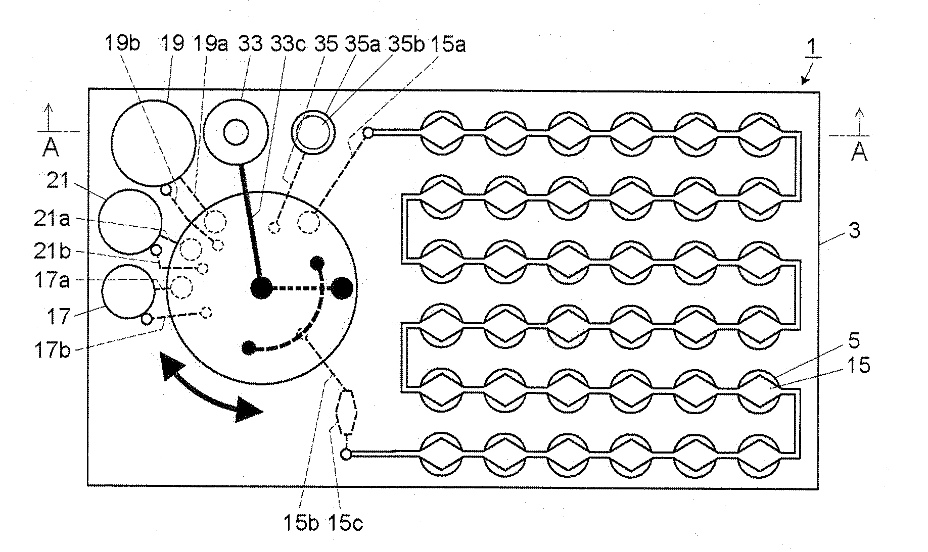
[0035]As described above, the reaction container plate according to the present invention includes a sealed reaction container, a reaction container channel connected to the reaction container, a sealed container provided separately from the reaction container, a sealed container channel connected to the sealed container, a syringe for sending a liquid, a switching valve for connecting the syringe to the reaction container channel or the sealed container channel, and a sealed container air vent channel of which one end is connected to the sealed container, and is processed using the reaction processing apparatus according to the present invention, and therefore, it is possible to prevent the entry of foreign matter from the outside of the reaction container plate and the pollution of an environment outside the reaction container plate with the liquid.
[0036]Further, since the reaction container plate includes the sealed container air vent channel communicating with the sealed container, it is possible to move a gas between the sealed container and the sealed container air vent channel when a liquid is injected into and sucked from the sealed container, thereby making it possible to smoothly inject and suck a liquid into and from the sealed container. Therefore, it is possible to prevent a phenomenon in which a liquid cannot be injected into and sucked from the sealed container due to an increase or decrease in the pressure in the sealed container.
[0037]In a case where the reaction container plate according to the present invention is intended to be used for measuring a gene-containing sample, the sample injected into the reaction container plate and then introduced into the reaction container can be processed in a closed system, and therefore, it is possible to prevent the pollution of an environment outside the reaction container plate and the pollution of the sample with foreign matter from outside the reaction container plate.
[0038]In the reaction container plate according to the present invention, a part of the sealed container air vent channel may be constituted from a narrow hole for maintaining the liquid-tightness of the sealed container in a state where there is no difference between the pressure in the sealed container and the pressure in the sealed container air vent channel. This makes it possible to prevent the leakage of a liquid to the outside through the sealed container air vent channel.
[0039]Further, the other end of the sealed container air vent channel may be hermetically sealed by being connected to a variable capacity part of which internal capacity is passively variable. This makes it possible to smoothly inject and suck a liquid into and from the sealed container because the internal capacity of the variable capacity part varies when the liquid is injected into and sucked from the sealed container. In addition, since the other end of the sealed container air vent channel is hermetically sealed, it is also possible to prevent the entry of foreign matter into the sealed container air vent channel from the outside and the leakage of the liquid to the outside.
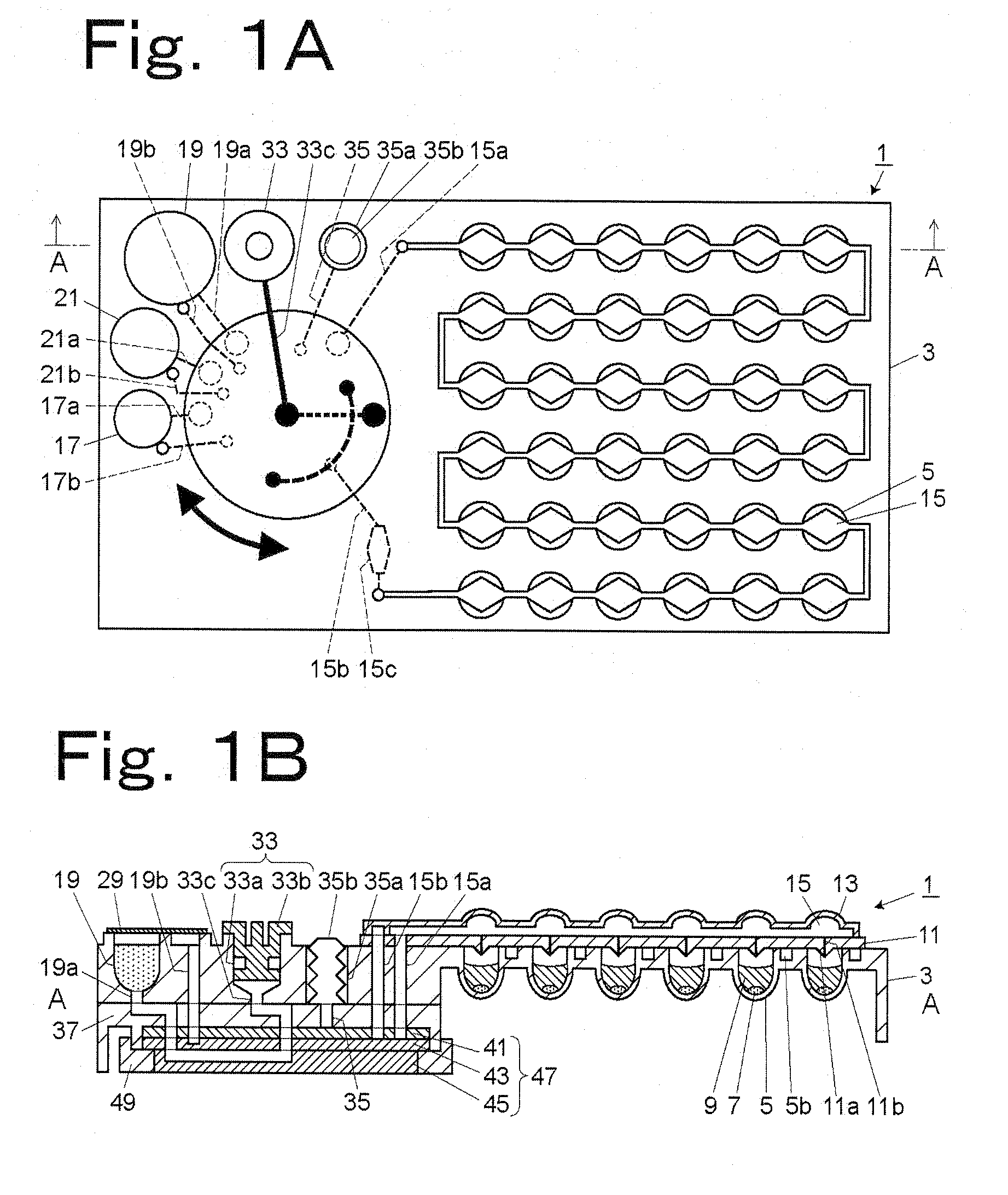
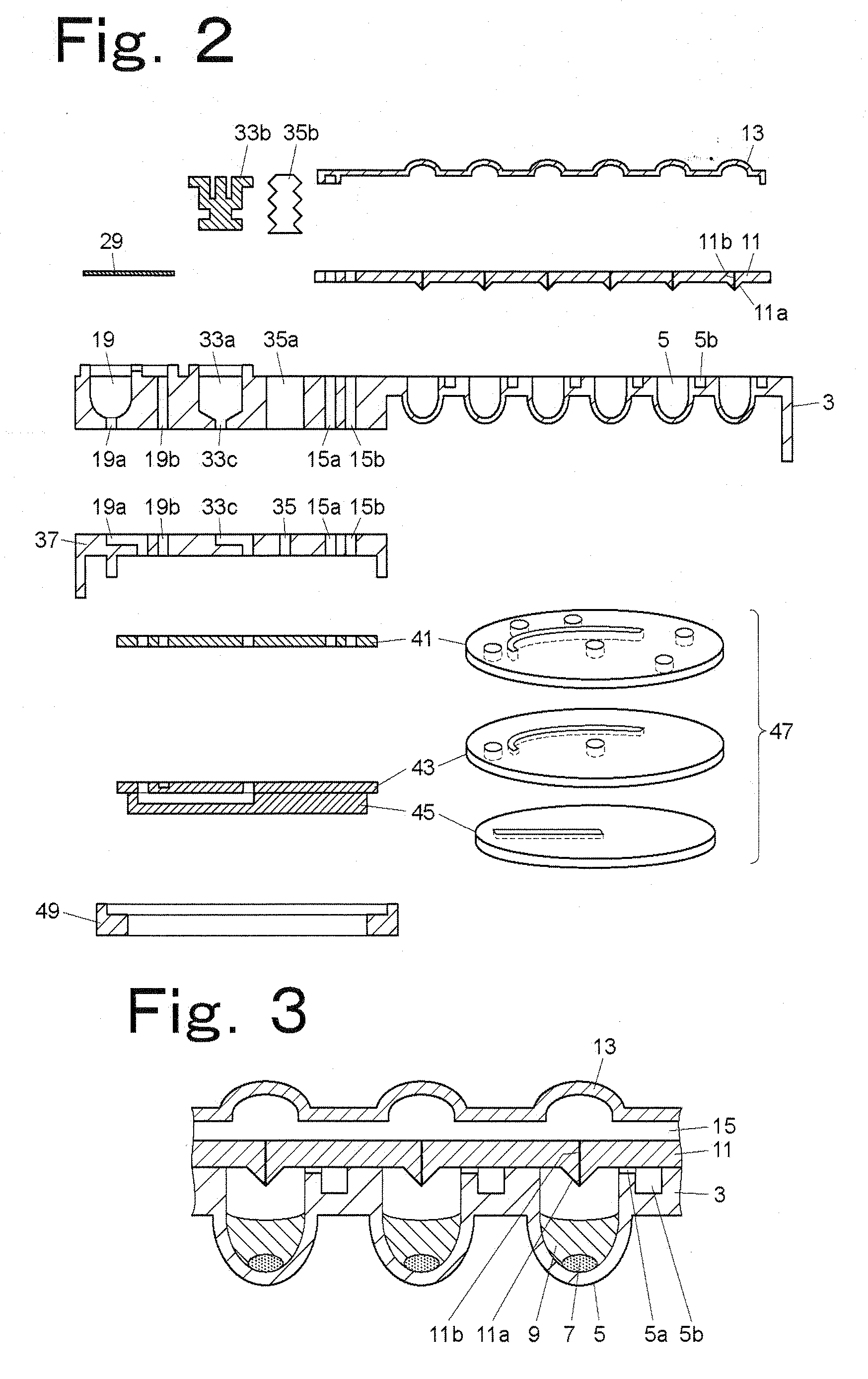
[0040]As one configuration example of the reaction container and the reaction container channel, the reaction container plate further including a container base constituted from a substrate and having the reaction container of which opening is provided in a surface of the substrate, a channel base provided on the surface of the container base so as to cover the reaction container to seal the reaction container and having a top surface, a back surface, and an introduction hole extending from the top surface to the back surface and located above the reaction container, and a channel cover provided on the channel base and having a hollow space in a surface thereof opposed to the channel base so that an introduction channel passing above the introduction hole is formed from the hollow space and the top surface of the channel base can be mentioned. In this case, the reaction container channel is constituted from the introduction channel and the introduction hole, the introduction channel can be hermetically sealed, the introduction hole does not allow the passage of a liquid at an introduction pressure applied to the inside of the introduction channel to introduce the liquid into the introduction channel but allows the passage of the liquid at an injection pressure much higher than the introduction pressure applied to the inside of the introduction channel to inject the liquid contained in the introduction channel into the reaction container, and the channel cover has a flexible portion in at least a part thereof corresponding to a part of the introduction channel so that after the liquid is introduced into the introduction channel, the flexible portion of the channel cover is biased toward the channel base to apply the injection pressure to the inside of the introduction channel to inject the liquid into the reaction container through the introduction hole.

Problems solved by technology

Therefore, there is a possibility that foreign matter will enter a sample from outside or, on the other hand, a reaction product will pollute a surrounding environment.

Method used


Image

  • Reaction container plate and reaction treatment apparatus
  • Reaction container plate and reaction treatment apparatus
  • Reaction container plate and reaction treatment apparatus

Examples


Embodiment Construction

[0150]FIG. 1A is a plan view of one embodiment of a reaction container plate according to the present invention, and FIG. 1B is a sectional view taken along the A-A line in FIG. 1A, which further includes a sectional view of a switching valve. FIG. 2 shows an exploded sectional view of the reaction container plate in the embodiment shown in FIG. 1A and an exploded perspective view of the switching valve. FIG. 3 is an expanded sectional view of reaction containers of the reaction container plate in the embodiment shown in FIG. 1A. FIG. 4A is an expanded plan view of a sample container, and FIG. 4B is a sectional view taken along the B-B line in FIG. 4A. FIG. 5A is an expanded plan view of a reagent container, and FIG. 5B is a sectional view taken along the C-C line in FIG. 5A.

[0151]With reference to FIGS. 1A to 5B, the reaction container plate according to one embodiment of the present invention will be described.

[0152]A reaction container plate 1 includes a plurality of reaction con...


PUM

PropertyMeasurementUnit
inner diameteraaaaaaaaaa
contact angleaaaaaaaaaa
thicknessaaaaaaaaaa

Abstract

Disclosed herein is a reaction container plate which prevents the entry of foreign matter from the outside and the pollution of an outside environment. A reaction container plate (1) includes a sealed reaction container (5), a reaction container channel (15) connected to the reaction container (5), a sealed container (17) provided separately from the reaction container (5), a sealed container channel (17a) connected to the sealed container (17), a syringe (33) for sending a liquid, a switching valve (47) for connecting the syringe (33) to the introduction channel (15) or the sealed container channel (17a), and a sealed container air vent channel (17b) of which one end is connected to the sealed container (17). When the syringe (33) is connected to the sealed container (17) via the switching valve (47) to inject a liquid contained in the syringe (33) into the sealed container (17) and to suck a liquid contained in the sealed container (17) into the syringe (33), a gas contained in the sealed container (17) is moved between the sealed container (17) and the sealed container air vent channel (17b).

Description

BACKGROUND OF THE INVENTION[0001]1. Field of the Invention[0002]The present invention relates to a reaction container plate suitable for use in various assays and analyses such as biological and biochemical assays, and general chemical analyses in the fields of medical care and chemistry, as well as a reaction processing apparatus for processing such a reaction container plate.[0003]2. Description of the Related Art[0004]As small reactors for use in biochemical assays or general chemical analyses, micro multi-chamber devices are used. Examples of such devices include micro container reaction container plates such as a microtiter plate constituted from a plate-shaped substrate having a plurality of containers formed in the surface thereof (see, for example, Japanese Patent Application Laid-open No. 2005-177749) and the like.[0005]Further, as a structure for dispensing a small amount of liquid which can quantitatively treat a small amount of liquid, a structure having a first channel,...

Claims


Application Information

Patent Timeline
Patent Type & Authority Applications(United States)
IPC IPC(8): C12M1/34B01J19/00C12M1/00B01J10/00
CPCB01J2219/00315G01N2035/00277B01J2219/00391B01L3/0268B01L3/5025B01L3/502738B01L2200/0605B01L2200/0684B01L2300/041B01L2300/046B01L2300/0829B01L2300/0864B01L2400/0478B01L2400/0481B01L2400/0487B01L2400/0605B01L2400/0611B01L2400/0622B01L2400/0644B01J2219/00364
Inventor HANAFUSA, NOBUHIRO
Owner SHIMADZU CORP
Why Eureka
Try Eureka