Medical Devices and Methods

a technology applied in the field of medical devices and methods, can solve the problems of difficult to reach the area to be treated, difficult to thread the needle of the arteries or other vessels, and difficult management of the guide wire in the operating room, and achieve the effect of small siz

Inactive Publication Date: 2010-02-04
GENESIS TECH
View PDF67 Cites 228 Cited by
  • Summary
  • Abstract
  • Description
  • Claims
  • Application Information

AI Technical Summary

Benefits of technology

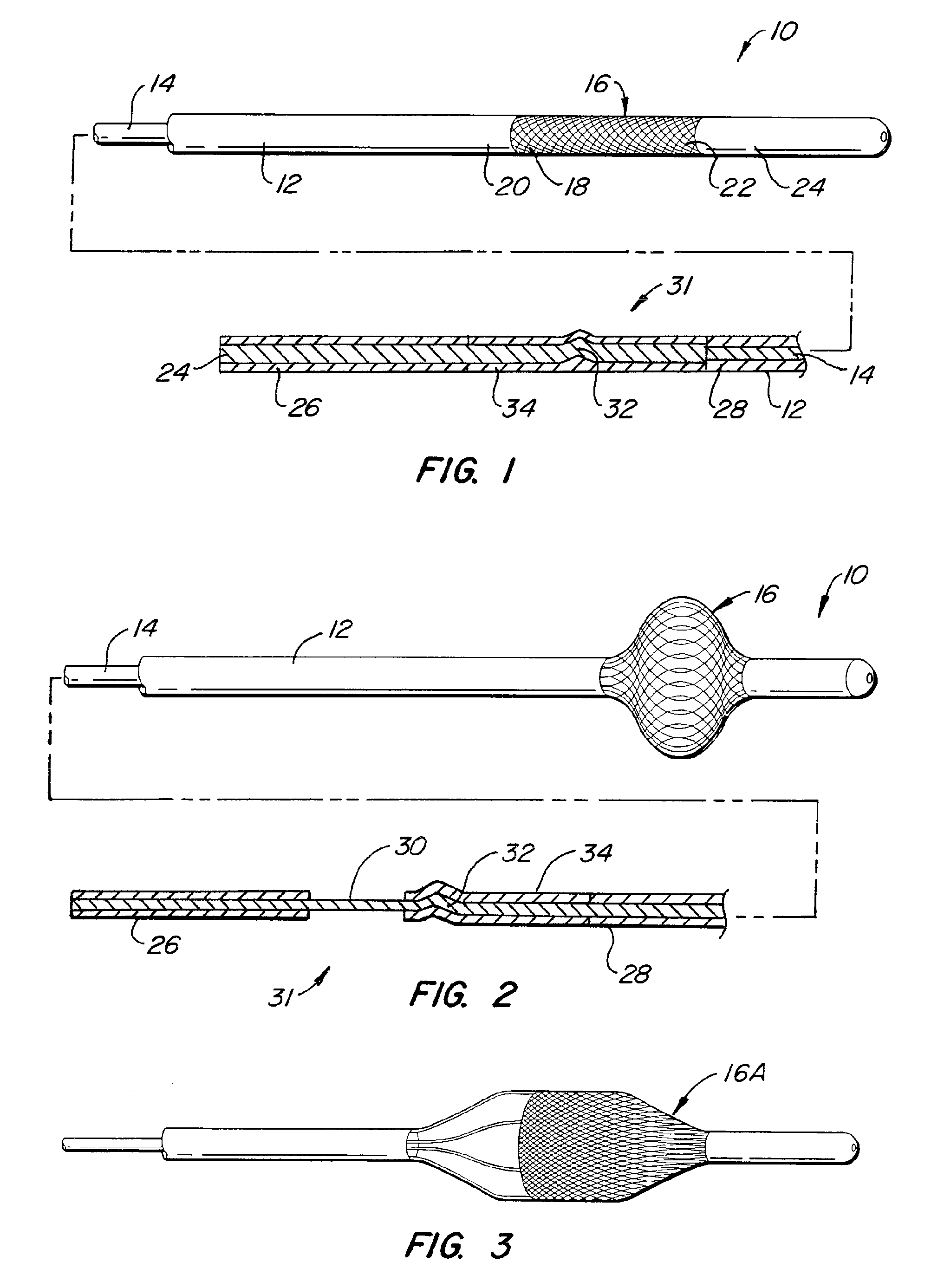
[0036]The support wire is a dual element support wire having a core and an annular shell that slides on the core. The distal end of the core is attached to the distal end of the annular braided element and the distal end of the shell is attached to the proximal end of the annular braided element. Thus movement of the core and shell relative to one another moves the braided element from a radially retracted position which is useful for insertion into the body to a radially expanded position which expands it to the sidewall of the tubular channel or against other tissue or matter within the body. When the annular braided element is in its radially co...

Problems solved by technology

Guide wire management in the operating room is problematic, and threading the needle of the arteries or other vessels including, but not limited to veins, intestines, fallopian tubes, etc. to reach the area to be treated is difficult.
Further, once the guide is in the desired location, it is often difficult to make certain that the it remains in that location.
Even further, once the guide wire, catheter, endoscope or other device is in the desired location and another device is placed over, through or along side it, the initially placed device has a tendency to move due to the forces exerted on it when other devices are using it as a guide.
A device, even though it performs a function in some improved manner, will not be widely used if it is considerably more costly than the alternatives available.
It will also tend to keep cost low.
Often this trauma is not realized immediately after surgery.
Extreme simplicity and a very simple procedure might over compromise safety.
Occlusive vascular disease is ...

Method used


Image

  • Medical Devices and Methods
  • Medical Devices and Methods
  • Medical Devices and Methods

Examples


Embodiment Construction

Clot Dragger Lock

[0136]One aspect of the instant invention relates to a locking mechanism for the blocking or engaging element. Of particular relevance is the locking mechanism of the engaging element. One such preferred embodiment incorporates an interference fit when and inner and outer slidable elongate member is used. Once deployed, the force required to keep the engaging element is usually small in relation to the force required to deploy (in the case of a non-self-expanding mechanism). In this case, a slight interference fit between the inner and outer slidable elongate members can be overcome easily by the interventionalist, but when the engaging or blocking element is deployed (partially or fully), the interference fit creates enough force of the system to remained deployed. The same invention could be used in the case where either the engaging element or blocking element is self-expanding, but in this case the interference fit would keep either element in the un-deployed, u...


PUM


Abstract

Medical devices include a catheter, a catheter/dilator assembly, an occluder, a rapid exchange dilator assembly, a funnel catheter, an anastomotic medical device, and associated methods.

Description

CROSS-REFERENCE TO RELATED APPLICATIONS[0001]This application is a continuation in part of Biological Passageway Occlusion Removal, application Ser. No. 10 / 747,813 filed 29 Dec. 2003 attorney docket number GTEC 1001-4, which is a continuation in part of Tissue Removal Device and Method, application Ser. No. 09 / 819,350 Filed 28 Mar. 2001, which is a continuation of Biological Passageway Occlusion Removal, application Ser. No. 09 / 189,574 Filed 11 Nov. 1998, now U.S. Pat. No. 6,238,412 issued May 29, 2001, which claims the priority of U.S. Provisional Application Ser. No. 60 / 065,118, filed on Nov. 12, 1997;[0002]This application is a continuation in part of Body Passageway Occluder and Method, application Ser. No. 10 / 765,564 filed 27 Jan. 2004, attorney docket number GTEC 1001-5, which is a continuation of Tissue Removal Device and Method, application Ser. No. 09 / 819,350 filed 28 Mar. 2001, which is a continuation of Biological Passageway Occlusion Removal, application Ser. No. 09 / 189,...

Claims


Application Information

Patent Timeline
IPC IPC(8): A61B17/221A61M29/00
CPCA61B6/502A61B2017/2215A61B10/0266A61B17/11A61B17/12022A61B17/12109A61B17/12113A61B17/12172A61B17/22004A61B17/221A61B17/32056A61B17/3421A61B18/14A61B19/38A61B19/54A61B2017/00287A61B2017/1107A61B2017/1135A61B2017/1205A61B2017/22034A61B2017/22067A61B2017/22079A61B2017/2212A61B2018/1407A61B2019/5404A61B2019/5408A61B2019/5462A61B17/12122A61M25/104A61B2017/00955A61B10/02A61B2090/3904A61B2090/3962A61B90/40A61B90/39A61B2090/3908A61M25/0119
Inventor DUBRUL, WILLIAM R.FULTON, III, RICHARD EUSTIS
Owner GENESIS TECH
Why Eureka
Try Eureka