Punch-Down Tool Blade with Extended Reach

a tool blade and extension technology, applied in the field of tools, can solve the problems of bulky tools blocking the view of the terminal clips of tradesmen, difficult to insert wires into the terminal clips of patch panels using a standard punch tool blade,

Inactive Publication Date: 2010-02-11
AMBRIGHT LEE
View PDF11 Cites 11 Cited by
  • Summary
  • Abstract
  • Description
  • Claims
  • Application Information

AI Technical Summary

Benefits of technology

[0008]The fifth and sixth exemplary embodiments show slidable locking collar mechanisms, where the locking collar may be moved to the end of the blade to be inserted into the punch-down tool, thereby retaining the slim non-tangling blade profile at the blade's working end.
[0010]One advantage of the present apparatus is to save the tradesman valuable time in installing networking services, thus allowing him or her to better compete in the workplace. In addition, time is saved by making the connection of physical networks of wires more efficient and reliable by allowing the blade tip to reach destination terminals without getting entangled, and dislodging other connected wires in the patch panel. The tradesman is saved not only the inconvenience of having to troubleshoot non-working data circuits caused by faulty patch panel connections, but also the stress, financial loss, and inconvenience of being called back to job sites to fix the problems and salvage relationships with dissatisfied customers.
[0011]Another advantage of one embodiment is that the punch-down blade allows the tradesman to keep the punch-down tool itself, as well as his or her hands away from all of the wires, thus providing the tradesman a greater view of the terminal clips for more accurate and successful placement of the device to make the proper connections, as well as enhanced safety. Consequently, the punch-down tool blade saves the tradesman the inconvenience of suffering strained arm, hand, and finger muscles and ligaments which readily occurs with standard punch-down tool blades while inefficiently seating and cutting wires in patch panels.

Problems solved by technology

Because the demand for such connections is increasing at such a large rate, patch panels increasingly become utilized to their full capacity; consequently, they become so crowded with wires that it often becomes difficult to insert wires into the terminal clip of a patch panel using a standard punch tool blade.
The proximity of the blade end being used to the bulky punch-down tool creates difficulties in connecting wires in the tight patch panels.
Difficulties include the blunt end of the tool precluding the tip of the device from gaining access to the proper punch-down point on a terminal clip of the patch panel, the blunt end dislodging other terminated wires in the panel when the installer attempts to add new wires to the patch panel, and the bulky tool blocking the tradesman's view of the terminal clips so that connecting wires to patch panels is prone to faulty or incorrect connections.
U.S. Pat. No. 7,266,878 shows a device that, while extending the overall length of a punch-down tool, still possess the above-mentioned problems.
Consequently, this large diameter still blocks the tradesman's access and view of the terminal clips, and the abrupt edges or ledges of the assembled tool readily snag adjacent wires when the tradesman attempts to use the device, thus providing little benefit in use.
Furthermore, the tradesman must carry several tips with him, and piece together the parts which can become easily lost when dropped, creating constant inconveniences to the tradesman.

Method used


Image

  • Punch-Down Tool Blade with Extended Reach
  • Punch-Down Tool Blade with Extended Reach
  • Punch-Down Tool Blade with Extended Reach

Examples


first embodiment

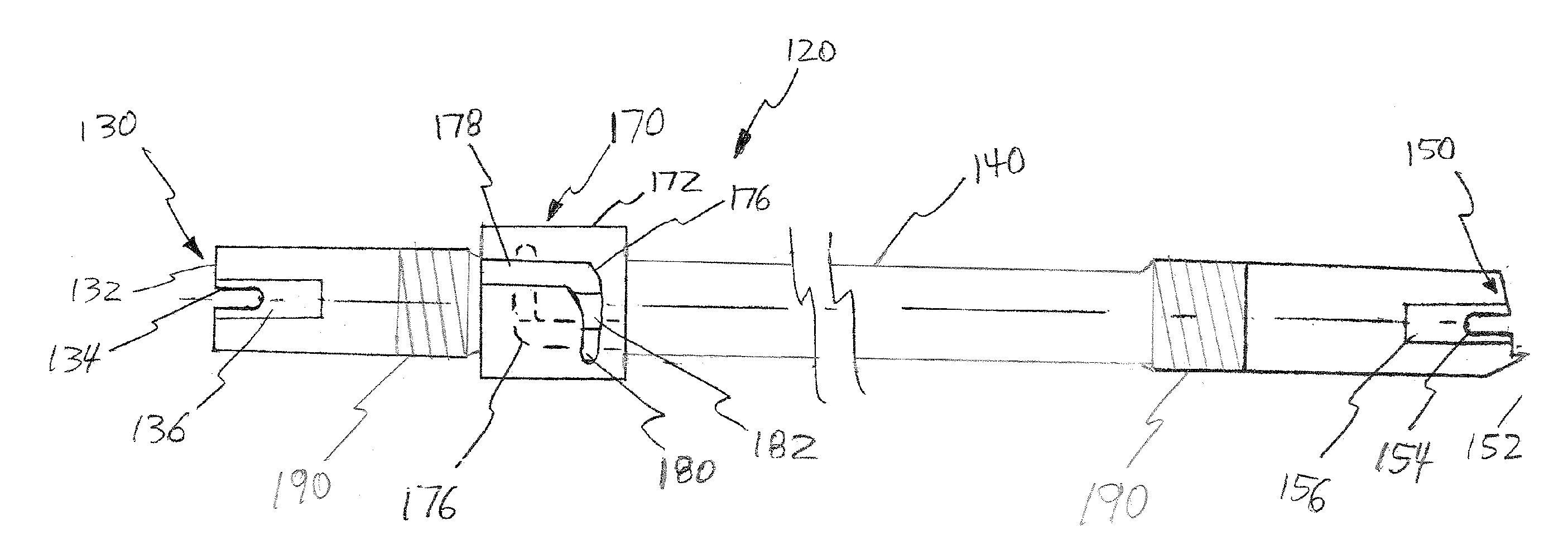
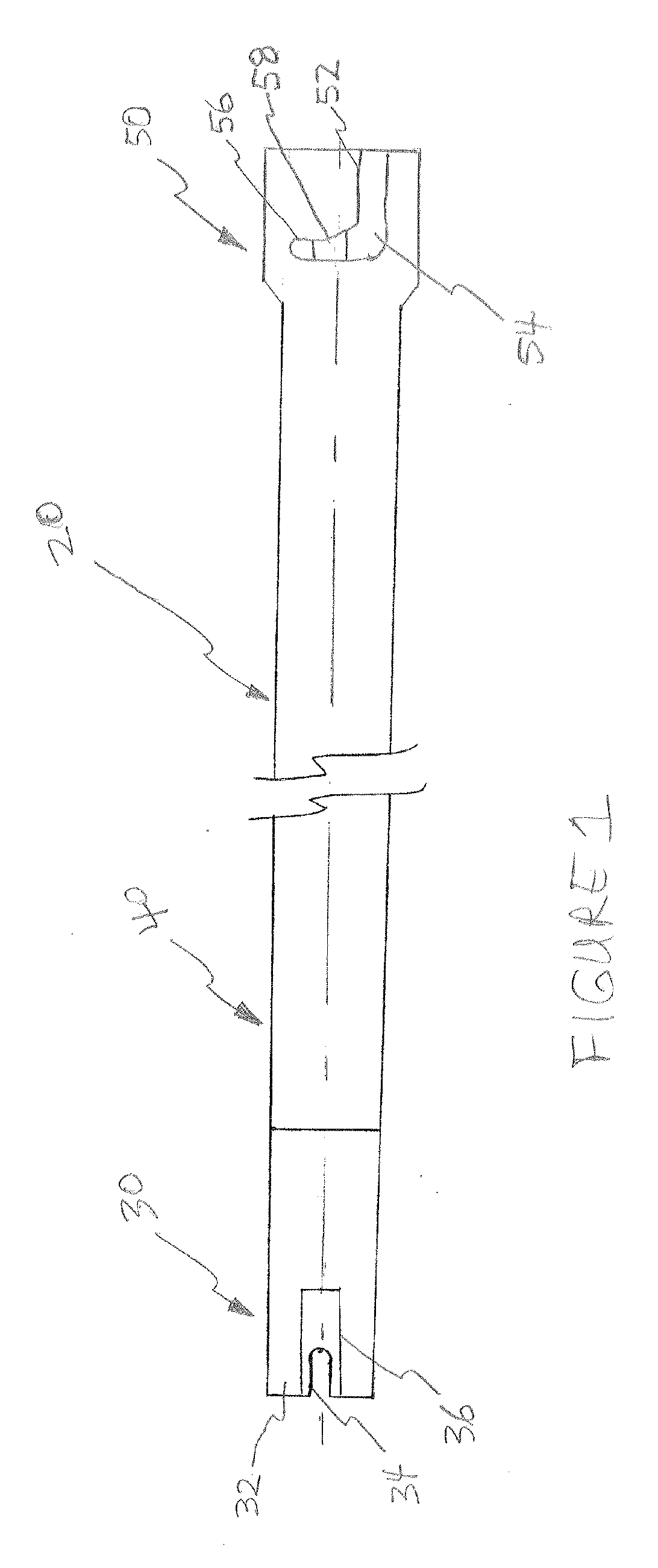
[0021]Referring to the drawings, where like reference numerals generally designate identical or corresponding parts throughout the several views, and more particularly to FIG. 1, there is shown a punch-down tool, more particularly, a punch-down tool blade well suited for seating wires into terminal clips in patch panels, designated generally by the numeral 20.

[0022]The punch-down tool blade 20 includes a working tip section 30, a long slender section 40, and a locking collar section 50. The working tip section 30 includes a seating edge 32, an elongated slot 34, and a groove 36 formed therein, which conforms to the shape of a terminal located on a terminal block (not shown) used in terminating telephone and data conducting wires. The long slender section 40 comprises a length of material having the structural rigidity to transfer forces down its axis without buckling. The locking collar section 50 comprises an L-shaped groove 52 having a lead-in detent 54 and a locking detent 56 on ...

third embodiment

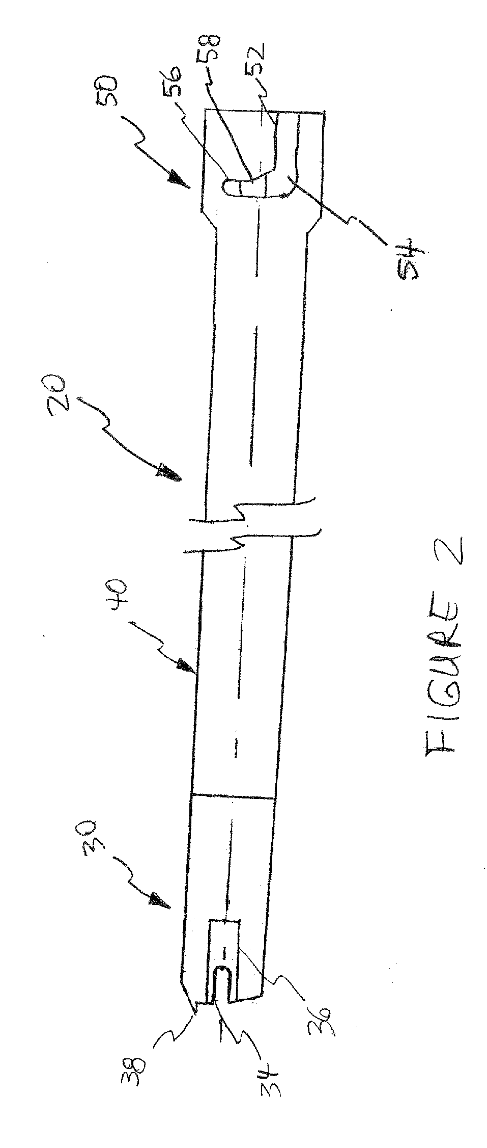
[0026]Referring now to FIG. 3, there is shown a punch-down tool blade having one end, which includes seating edge 32, well suited for the seating wires to terminal clips in patch panels, and another end, which includes seating and cutting edge 38, well suited for the seating and cutting of wires in patch panels. This embodiment incorporates a fixed locking collar section 50 located near the blade tip used less frequently, which is usually the seating tip (most connections are typically of the seating and terminating type). Please note that in FIG. 3 the fixed locking collar section 50 is shown adjacent the blade edge with the seating tip; however, in a related embodiment the fixed locking collar section 50 may be located adjacent the blade edge with the seating and cutting tip. In this related embodiment the L-shaped groove would be oriented such that the “L” in the figure would be pointing up towards the top of the figure to show that fixing the punch-down tool blade to the punch-d...


PUM

PropertyMeasurementUnit
lengthaaaaaaaaaa
lengthaaaaaaaaaa
lengthaaaaaaaaaa

Abstract

Disclosed is a punch-down tool blade suited for seating, and seating and cutting data transmission and telephony wires into crowded patch panels. Also disclosed are embodiments of an elongated punch-down tool blade having a slidable locking collar which may be used in reversibly locking a punch-down tool blade with either the seating tip being used as the working tip or the seating and cutting tip used as the working tip without compromising both the ability of the tool tip to gain access to terminating clips or the tradesman's visibility of terminating clips so that patch panels may be efficiently and accurately wired while providing enhanced safety and decreased worker fatigue.

Description

FIELD[0001]The invention generally pertains to the field of tools used in assembling data / telephony networks, and more particularly to punch-down tools used to insert or insert and terminate transmission wires into patch panels.BACKGROUND[0002]The information superhighway has grown exponentially over the past two decades. The internet has created a multitude of ways in which people across the earth can communicate. Junction boxes, or patch panels are commonly used in data rooms to make the multitude of physical connections between end-user lines with various types of data switches, bridges, and routers, which in turn are connected to local internet service providers, regional access routers to high bandwidth back-haul providers across long distances to distant regional access providers, internet service providers and ultimately distant end users. Punch-down tools are used to connect signal wires into such patch panels. Two common patch panel types are 110 data patch panels and 66 ca...

Claims


Application Information

Patent Timeline
Patent Type & Authority Applications(United States)
IPC IPC(8): H01R43/01B26B9/02
CPCB26F1/32H01R43/015Y10T29/53257Y10T29/5151Y10T29/53222
Inventor LEE, BOYD M.AMBRIGHT, JOSEPH
Owner AMBRIGHT LEE
Why Eureka
Try Eureka