Disposable Pipette Tip

a pipette tip and disposable technology, applied in the field of pipettes and automated liquid handling systems, can solve the problems of over-center locking engagement and ergonomic, and achieve the effects of facilitating reliable engagement of the sealing ring, reducing insertion force, and maintaining the roundness of the sealing area

Active Publication Date: 2010-02-11
INTEGRA BIOSCI CORP
View PDF51 Cites 58 Cited by
  • Summary
  • Abstract
  • Description
  • Claims
  • Application Information

AI Technical Summary

Benefits of technology

[0008]The lower sealing area on the mounting shaft extends below the stop member. The lower sealing section is preferably tapered in a frustoconical shape, but can be cylindrical, depending on the geometry of the matching pipette tip. Similarly, the pipette tip preferably includes a sealing ring in a sealing area located below the circumferential shelf at the upper end of the pipette tip barrel. The shape of the tip sealing area should match the shape of the lower sealing section of the mounting shaft. The circumferential shelf on a pipette tip isolates the distortion of the collar from the sealing area when the tip is mounted on the mounting shaft, thus maintaining the roundness of the sealing area (i.e. a circular circumference for the inside surface of the pipette tip barrel) in which the sealing ring is located. This is important in order to facilitate reliable engagement of the sealing ring around the lower sealing section of the mounting shaft.
[0009]As the mounting shaft is pushed into the tip collar, the first point of contact is where the leading edge of the mounting shaft, i.e. the lower sealing section, enters through the circumferential shelf in the pipette tip and contacts the sealing ring. As the mounting shaft is further depressed into the pipette tip bore, sealing ring interference increases simultaneously as the ramp area of the lobes of the mounting shaft engages the locking ring on the tip collar to distort the upper portion of the collar our of round. As mentioned, while the overall insertion force is relatively light and ergonomic, the force increases noticeably and provides tactile feedback to the user that the tip is almost fully mounted. This increase in insertion force continues until the stop member on the mounting shaft engages the circumferential shelf on the pipette tip to abruptly stop further movement of the mounting shaft into the tip, at which point the lobes also snap engage under the locking ring in the collar bore. Thus alerting the user not to use additional, excessive force to mount the tip. These interrelated mounting conditions result in a secure stable mount with consistent sealing at the sealing ring. Alternatively, the initial engagement of the sealing ring can be staggered with respect to the engagement of the locking ring in order to lessen insertion force.
[0010]Moreover, the tip requires relatively low ejection force. When the pipette stripper sleeve pushes against the upper end of the tip collar, a relatively small ejection force is required to release the locking ring on the collar from the locking lobes on the mounting shaft. The flexing of the collar in its distorted shape when it is locked over the mounting shaft lobes stores energy. When the tip is released from the lobes, the combination of the pressure from the stripper and the release of the stored energy throw the tip from the mounting shaft, thereby facilitating convenient ejection of the tips from the mounting shaft after use.
[0011]In some circumstances, it may be desirable to further lessen tip insertion and injection forces, such as is particularly desirable with hand-held multi-channel pipettors. In order to achieve this objective, it may be desirable to lessen the amount of interference between the pipette tip and the mounting shaft prior to full insertion of the mounting shaft into the pipette tip. In one embodiment of the invention, this is achieved by reducing the diameter of the mounting shaft below the sealing area on the mounting shaft so that there is little or no interference with the circumferential sealing ring on the pipette tip, and by further providing the sealing area on the mounting shaft with a frustoconical shape to facilitate effective sealing engagement of the circumferential sealing ring on the pipette tip with the mounting shaft. This embodiment is particularly useful for small volume pipette tips, such as 12.5μ liter or 125μ liter pipette tips. The purpose of the frustoconical sealing zone is to accommodate a preselected vertical range of travel, such as 0.025 to 0.030 inches of vertical travel, for which the circumferential sealing ring on the pipette tip can effectively engage the frustoconical sealing area on the mounting shaft. The preferred amount of taper in the frustoconical sealing area on the mounting shaft is between 4° and 7° included angle, and is preferably calculated to accommodate for normal manufacturing tolerances for molded pipette tips. In other words, pipette tips in which the diameter of the circumferential sealing ring is relatively small within normal manufacturing tolerances will typically engage the lower edge of the frustoconical sealing area on the mounting shaft, whereas pipette tips with larger circumferential sealing rings within normal manufacturing tolerances will engage slightly higher in the frustoconical sealing area on the mounting shaft.
[0012]In another embodiment that is particularly well suited to reduce insertion and ejection forces, the diameter of substantially all of the lower portion of the mounting shaft is reduced such that there is little or no interference between the circumferential sealing ring on the pipette tip and the mounting shaft, thereby rendering the circumferential sealing ring a stabilization ring rather than a sealing ring. In this embodiment, the mounting shaft has an annular groove containing a sealing ring, preferably an O-ring made of flouroelastomeric material to effectuate a reliable seal with the pipette tip. This embodiment has been found to be particularly effective for pipettors having relatively large pipette tips, such as 300μ liters or 1250μ liters. The sealing O-ring is on the mounting shaft, preferably located so that it seals against the upper end of the barrel of the pipette tip. Preferably, in order to lessen long term wear on the O-ring as well as insertion and ejection forces, the center line of the O-ring will reside no more than about 0.03 inches into the barrel of the pipette tip below the circumferential shelf on the pipette tip.

Problems solved by technology

This configuration results in an ergonomic, over-center locking engagement.

Method used


Image

  • Disposable Pipette Tip
  • Disposable Pipette Tip
  • Disposable Pipette Tip

Examples


Embodiment Construction

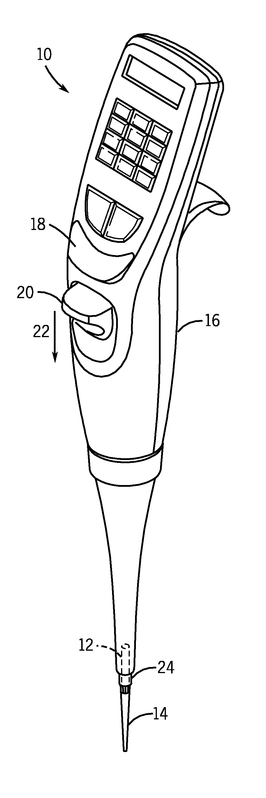
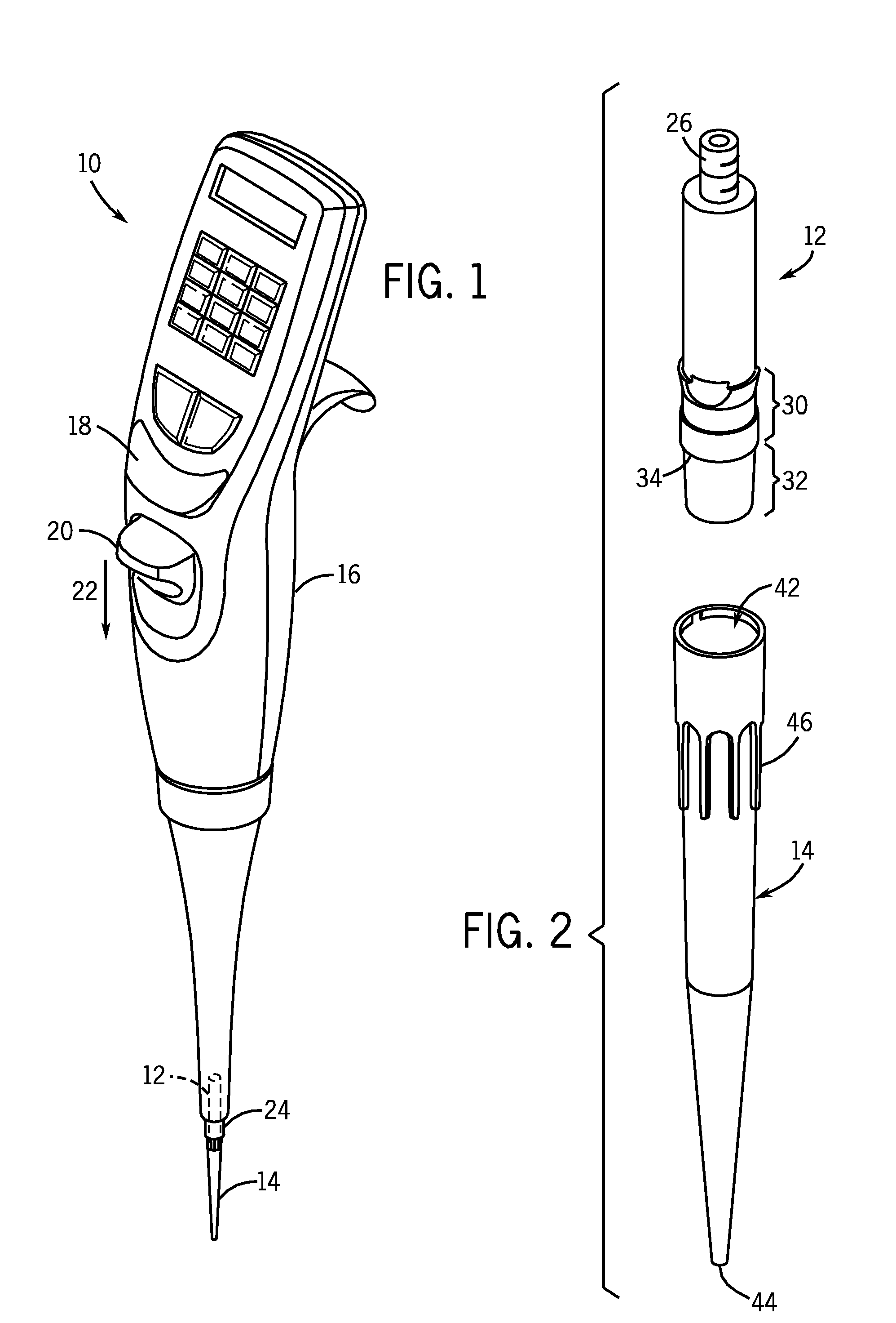
[0030]FIG. 1 illustrates a hand-held, electronic air displacement pipette 10 that incorporates a pipette mounting shaft 12 and a disposable pipette tip 14 constructed in accordance with the preferred embodiment of invention. The pipette 10 includes a housing 16 designed to be held in the palm of the user. Internal components of the pipette (not shown) drive a piston that extends through a seal assembly to displace air within an aspiration and dispensing cylinder. The pipette mounting shaft 12 is threaded or otherwise attached to the lower end of the pipette such that it is in fluid communication with the aspiration and dispensing chamber. The attachment of the mounting shaft to the pipette is not particularly relevant to the concepts of the invention, and is well known in the art. Button 18 is provided for the user to instruct the electronic pipette to aspirate and dispense. The pipette 10 also includes a lever 20 that is actuated in the direction of arrow 22 to move an ejection mec...


PUM


Abstract

In one aspect, the invention relates to a pipette tip mounting shaft configuration and a disposable pipette tip having a matching configuration. The mounting shaft includes a locking section located above a lower sealing section. The locking section has outwardly extending locking lobes located above a stop member and a lower sealing section located below the stop member. In certain embodiments, the diameter of the mounting shaft below the stop member is reduced in order to lessen insertion and ejection forces, which is particularly helpful for hand-held multi-channel pipettors. In these embodiments, the lower sealing section contains either a frustoconical sealing section, or an annular groove and a sealing ring, such as a flouroelastomeric O-ring seal. When the mounting shaft is fully inserted into the collar of the mating disposable pipette tip, the tip locks onto the mounting shaft. The bore of the pipette tip includes a circumferential shelf or shoulder separating its upper collar from the tip sealing area which is located below the circumferential shelf. The tip collar preferably includes a locking ring located at or near the upper opening for the mounting shaft. The dimensions of the collar, and in particular the distance between its circumferential shelf and the locking ring, are selected to match the dimensions of the mounting shaft between the stop member and the upper end of the locking lobes, thus locking the pipette tip in a secure, reliable position and orientation while using ergonomic insertion and ejection forces. The locking lobes preferably include a ramp portion that gently flexes and distorts the pipette tip collar out of round as the mounting shaft is inserted in the pipette tip, rather than stretching the tip collar. The circumferential shelf on the pipette tip between the tip collar and the barrel isolates the sealing area at the upper end of the barrel from distortion, thus facilitating reliable sealing engagement between the lower sealing section of the mounting shaft and the sealing ring in the upper end of the barrel of the pipette tip.

Description

CROSS REFERENCE TO RELATED APPLICATION[0001]This application is a Continuation-In-Part of U.S. patent application Ser. No. 11 / 552,384, which is entitled “Locking Pipette Tip And Mounting Shaft”, by Gregory Mathus, Terrence Kelly and Richard Cote filed on Oct. 24, 2006, which is assigned to the assignee of the present application.FIELD OF THE INVENTION[0002]The invention relates to improvements in pipettes and automated liquid handling systems. More specifically, the invention relates to a configuration for pipette tip mounting shafts and disposable pipette tips that provides robust sealing engagement with low insertion and ejection forces as well as enhanced resistance to unintentional removal, and maintains the mounted tip in optimum position and orientation when the tip is mounted on the pipette tip mounting shaft.BACKGROUND OF THE INVENTION[0003]The use of disposable pipette tips with hand-held pipettes and automated liquid handling systems is well known. Disposable pipette tips ...

Claims


Application Information

Patent Timeline
Patent Type & Authority Applications(United States)
IPC IPC(8): B01L3/02
CPCB01L3/0279B01L2200/023B01L2200/025B01L2200/0689Y10T436/2575B01L2300/027B01L3/0275B01L3/0217B01L2200/087Y10T137/0318
Inventor MATHUS, GREGORYKELLY, TERRENCECOTE, RICHARD
Owner INTEGRA BIOSCI CORP
Why Eureka
Try Eureka