Coating and processing apparatus and method

a technology of coating and processing apparatus, applied in the direction of photomechanical apparatus, cleaning using liquids, instruments, etc., can solve the problems of cross contamination, significant influence on the accuracy of wiring width, and low dimensional accuracy of mask pattern

Inactive Publication Date: 2010-02-11
TOKYO ELECTRON LTD
View PDF10 Cites 9 Cited by
  • Summary
  • Abstract
  • Description
  • Claims
  • Application Information

AI Technical Summary

Benefits of technology

[0016]According to the present invention, since a quadrangular substrate, spin chuck and rinse liquid supply unit are synchronously rotated, the centrifugal force on and surface tension of the rinse liquid work in concert, with the result that the resist deposit can be efficiently removed from the back and side surfaces of the corner portions of a substrate. Therefore, when the corner portions of the substrate are held by a transfer arm member, the resist solution cannot be transferred to the transfer arm member. In this manner, cross contamination via the transfer arm member can be effectively prevented.
[0021]Furthermore, the guide channels are through-holes obliquely passing outward from the lower surface to the upper surface of the holding plate for smoothly supplying the rinse liquid applied to the lower surface of the holding plate by the nozzle, toward the back surface of the substrate.
[0031](c) supplying a rinse liquid to a back surface of the substrate from a rinse liquid supply unit while rotating the spin chuck and the rinse liquid supply unit synchronously around the vertical axis, thereby permitting the rinse liquid to reach the corner portions of the substrate with the help of centrifugal force to wash away the coating solution.
[0034]The guide channels are through-holes radially arranged on a concentric circle around a rotation center of the holding plate. Further, the guide channels are through-holes obliquely passing outward from the lower surface to the upper surface of the holding plate for smoothly directing the rinse liquid sprayed on the lower surface of the holding plate by the nozzle toward the back surface of the substrate.

Problems solved by technology

When the dimensional accuracy of a mask pattern is low, the accuracy of wiring width is significantly affected in all semiconductor wafers exposed to light with the pattern as a mask.
However, when a resist solution is applied to a mask substrate by use of a conventional apparatus, the resist solution enters the recess, attaches to the side surface and back surface of the mask substrate and the attached resist solution is transferred to a transfer arm member, causing cross contamination.
The cross contamination frequently occurs particularly at the corner portions of the substrate.

Method used


Image

  • Coating and processing apparatus and method
  • Coating and processing apparatus and method
  • Coating and processing apparatus and method

Examples


Embodiment Construction

[0062]Preferable embodiments of the present invention will be explained with reference to the accompanying drawings.

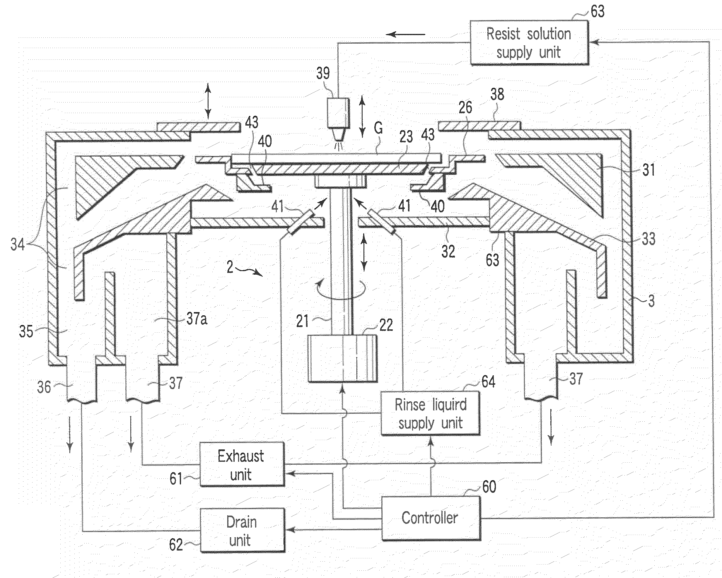
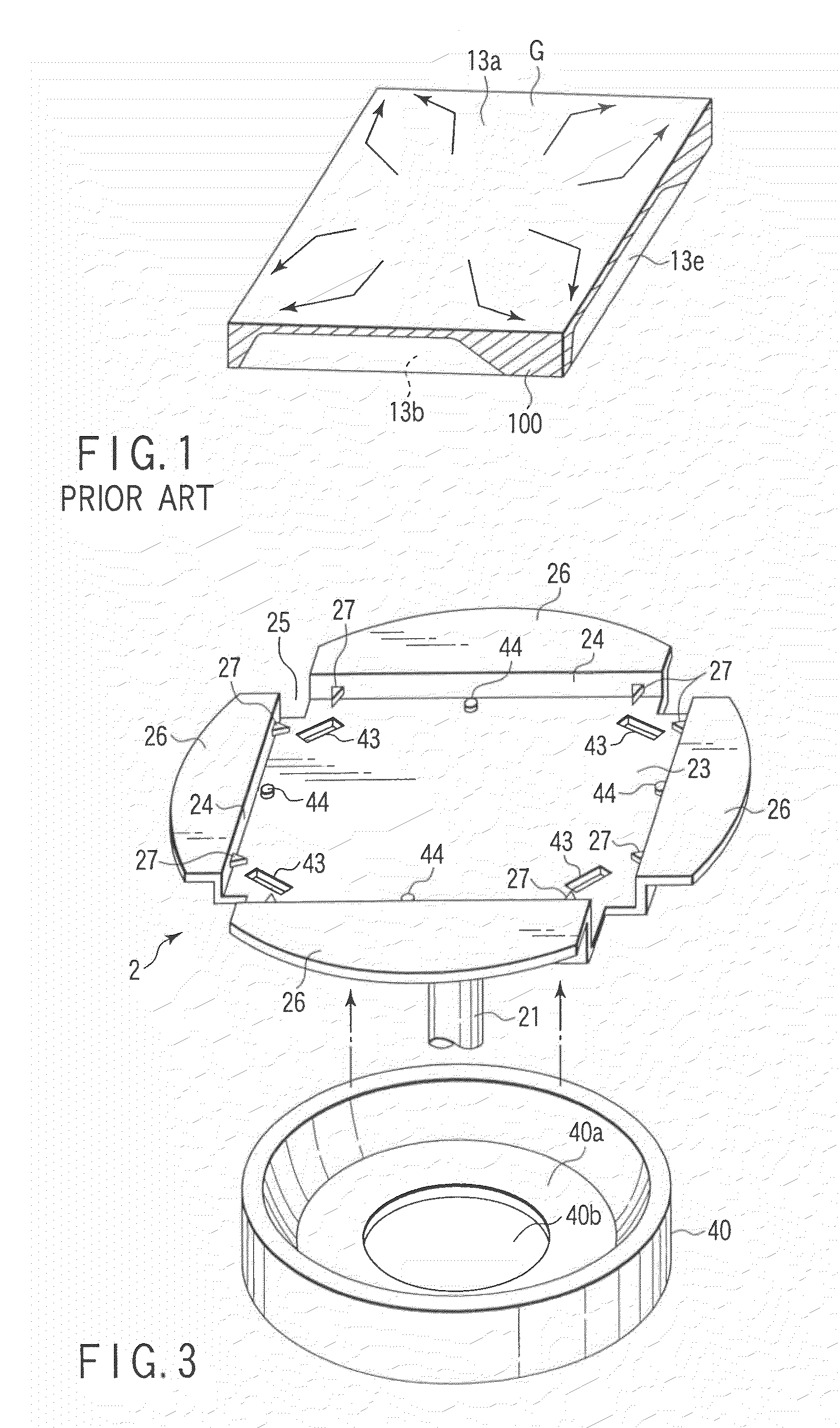
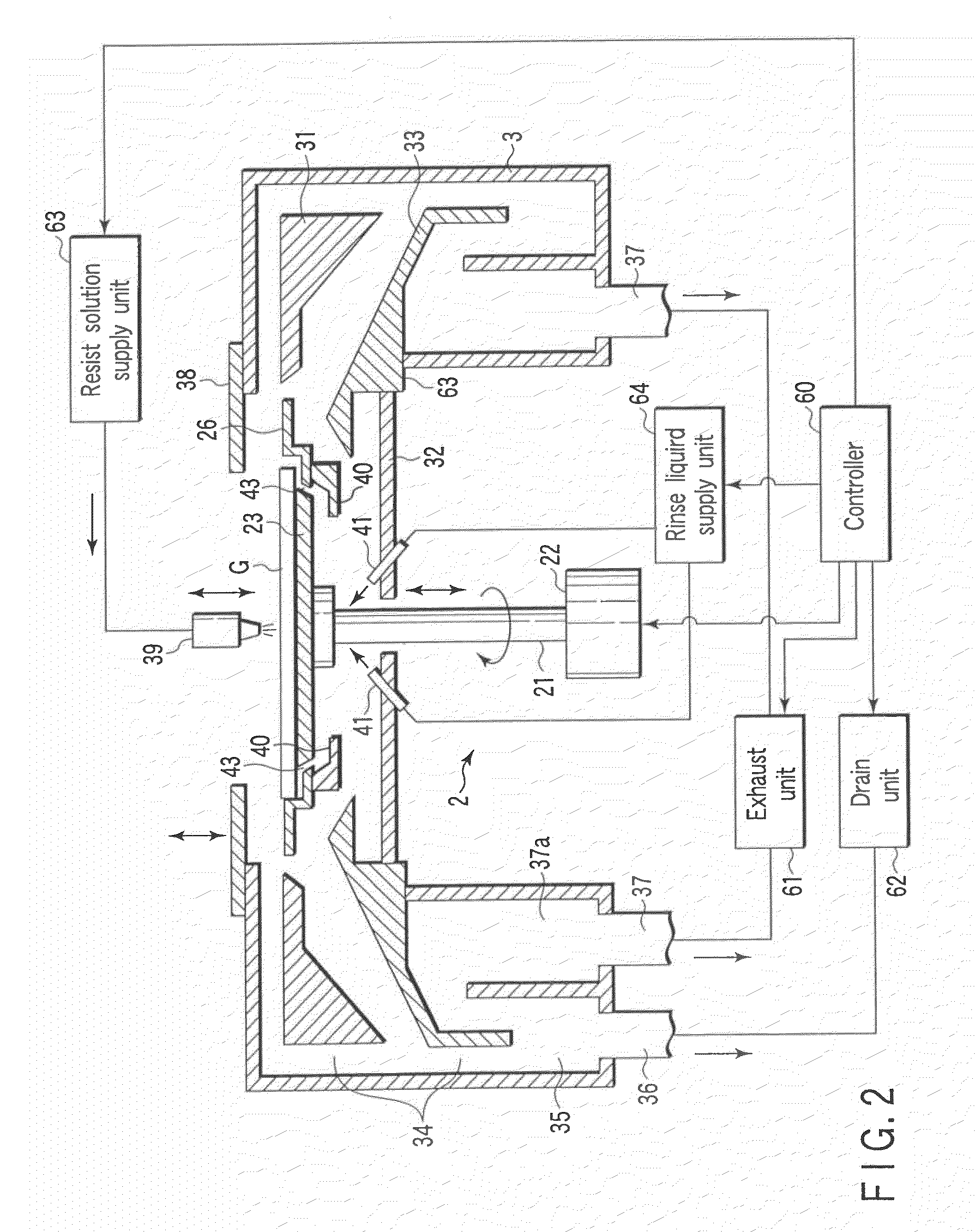
[0063]As shown in FIG. 2, a spin chuck 2 is accommodated within a cup 3 of the coating and processing apparatus. The spin chuck 2 receives a mask substrate G (work piece) from a transfer arm mechanism 5 shown in FIG. 7 and performs predetermined coating treatment to the substrate G. The mask substrate G (work piece) is formed of square quartz glass having a side length L1 of 152±0.4 mm, on which a chromium oxide (Cr2O3) coating film is applied, and further on the chromium oxide, a resist coating film formed. The thickness of the mask substrate G is a quarter inch (6.35±0.1 mm) and the projected length of the C plane is 0.2 to 0.6 mm.

[0064]The spin chuck 2 has a holding plate 23 for holding a quadrangular substrate G. The holding plate 23 is connected to a driving unit 22 via a rotation axis 21. The driving unit 22, which is controlled by a controller 60, rotates the sp...


PUM

PropertyMeasurementUnit
side length L1aaaaaaaaaa
thicknessaaaaaaaaaa
outer diameteraaaaaaaaaa

Abstract

There is provided a coating and processing apparatus including a spin chuck horizontally holding a quadrangular substrate and rotating the substrate in a horizontal plane, a coating solution nozzle for supplying a coating solution to a front surface of the substrate horizontally held by the spin chuck, and a solvent supply mechanism provided in the spin chuck for supplying a solvent to a back surface of the substrate, in which the solvent supplied to the back surface of the substrate is allowed to reach the back surface and side surface of each of corners of the substrate by centrifugal force, thereby removing the coating solution attached.

Description

CROSS-REFERENCE TO RELATED APPLICATIONS[0001]This application is a divisional of U.S. application Ser. No. 10 / 795,269, filed on Mar. 9, 2004, and is based upon and claims the benefit of priority from prior Japanese Patent Application No. 2003-063851, filed Mar. 10, 2003. The entire contents of each of the above-listed applications are incorporated herein by reference.BACKGROUND OF THE INVENTION[0002]1. Field of the Invention[0003]The present invention relates to a coating and processing apparatus for applying a coating solution and removing the coating solution undesirably attached on the back and side surfaces of a mask substrate to be subjected to a light exposure step of a photolithographic process for a semiconductor device, and a method of coating and removing the coating solution.[0004]2. Description of the Related Art[0005]In manufacturing a semiconductor device and a liquid crystal display (LCD) device, a predetermined pattern is photolithographically formed on a photoresist...

Claims


Application Information

Patent Timeline
Patent Type & Authority Applications(United States)
IPC IPC(8): B05D3/12B05C11/08G03F7/16B05C11/10B05D1/00B05D1/40H01L21/00H01L21/027H01L21/687
CPCB05D1/005G03F7/162H01L21/6875H01L21/68721H01L21/68735H01L21/6715
Inventor KOBAYASHI, SHINJIMIYAMOTO, TETSUSHIHAMADA, MASAHITOKANEDA, MASATOSHI
Owner TOKYO ELECTRON LTD
Why Eureka
Try Eureka