Imaging of deep structures of reliefs for shallow relief embossing

a deep relief and embossing technology, applied in the field of embossing materials, can solve the problems of reducing the quality of the product, uv casting, less than 400 nm, and cumbersome creation of physical/actual textur

Active Publication Date: 2010-02-11
ILLINOIS TOOL WORKS INC
View PDF6 Cites 1 Cited by
  • Summary
  • Abstract
  • Description
  • Claims
  • Application Information

AI Technical Summary

Benefits of technology

[0006]A relief is incorporated into a photodefineable surface by making a transparent mold of a relief surface, such as brushed metal, and then shining one or more lights through the mold such that the relief in the mold will map onto a photoresist surface. Mapping is created by different amounts of diffraction and refraction of the light, such as laser light/beams or other light sources pr...

Problems solved by technology

A textured pattern, also known as a relief, having a deep or thick profile greater than 400 nm usually cannot be embossed directly onto a substrate using traditional holographic embossing techniques, such as embossing rollers, because the ...

Method used


Image

  • Imaging of deep structures of reliefs for shallow relief embossing
  • Imaging of deep structures of reliefs for shallow relief embossing
  • Imaging of deep structures of reliefs for shallow relief embossing

Examples


Embodiment Construction

[0015]While the present invention is susceptible of embodiment in various forms, there is shown in the drawings and will hereinafter be described a presently preferred embodiment with the understanding that the present disclosure is to be considered an exemplification of the invention and is not intended to limit the invention to the specific embodiment illustrated.

[0016]It should be further understood that the title of this section of this specification, namely, “Detailed Description Of The Invention”, relates to a requirement of the United States Patent Office, and does not imply, nor should be inferred to limit the subject matter disclosed herein.

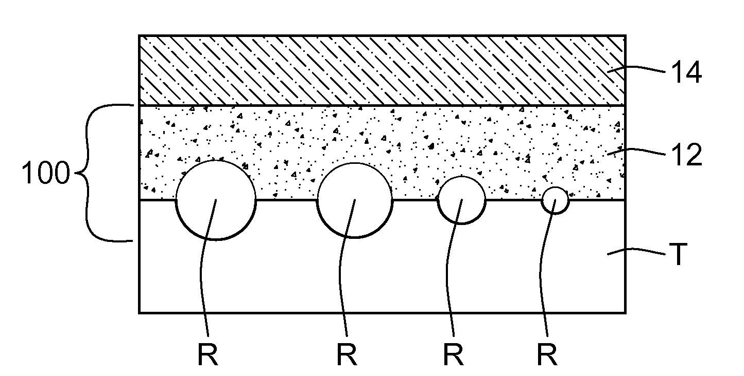
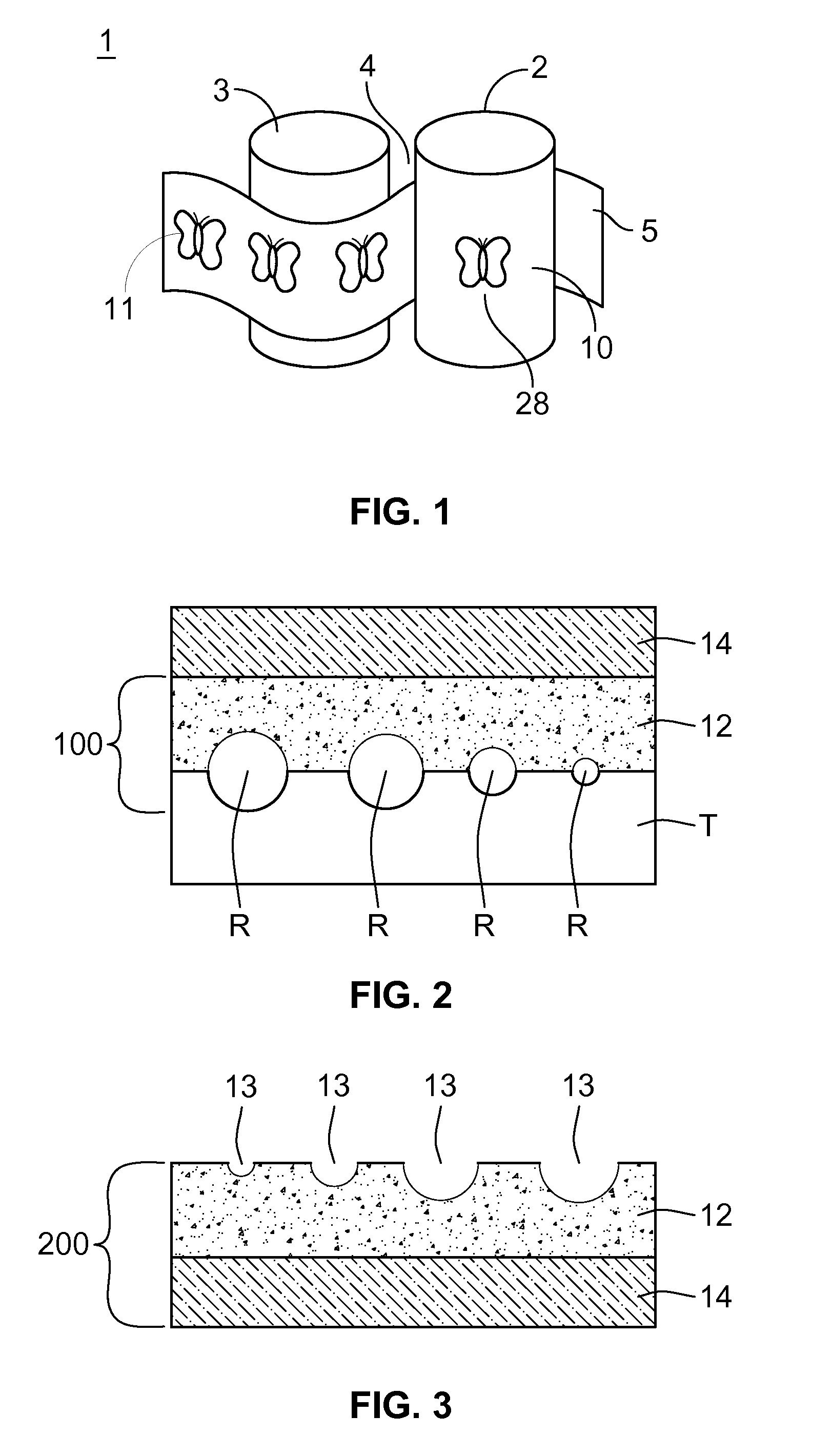
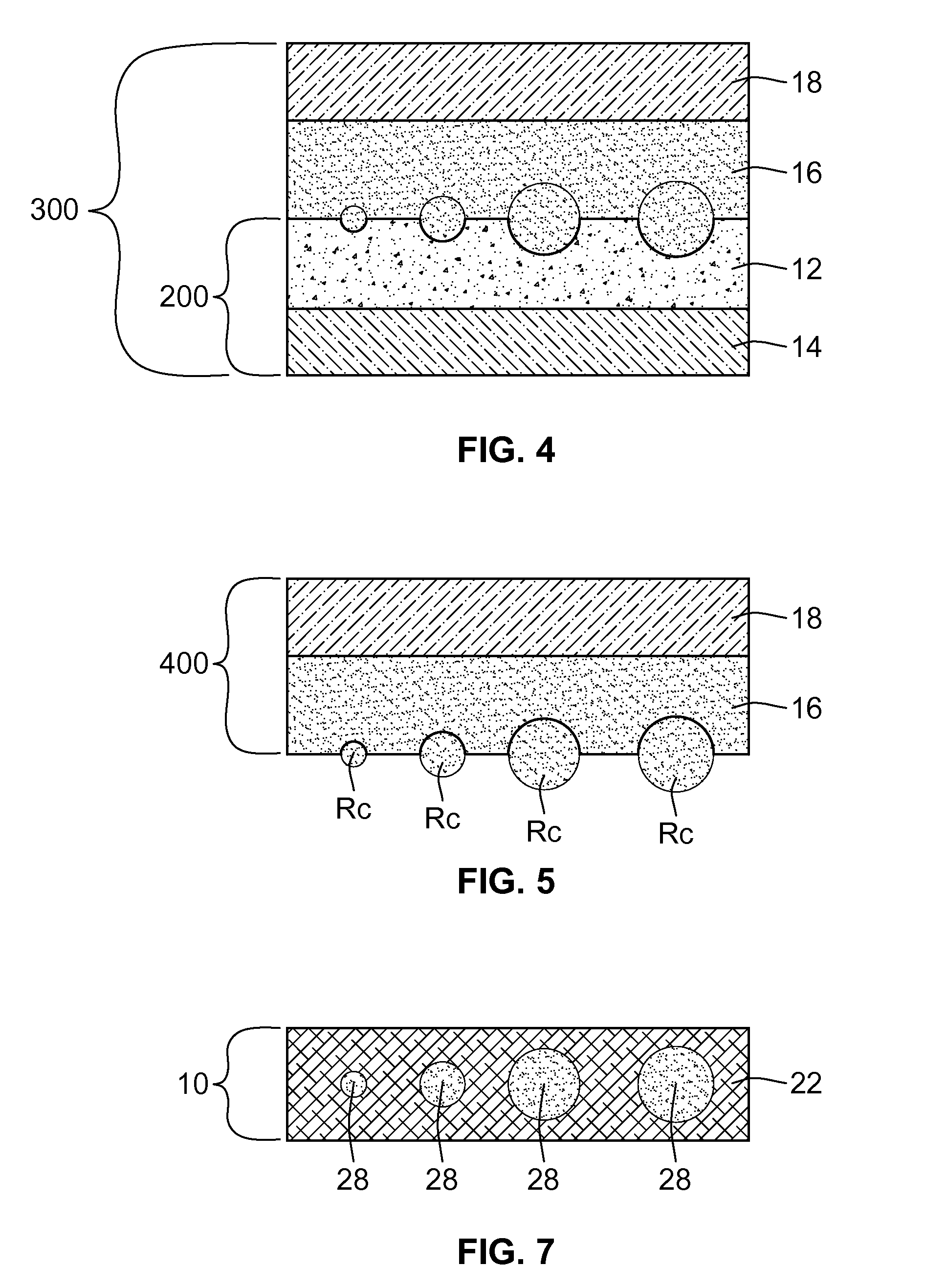
[0017]A variety of deep structured decorative patterns originate with mechanical relief, such as polishing or grinding, or chemical processes such as etching. The present method incorporates a deeply patterned or textured etching or relief into a film embossing shim to simulate the look of the deep pattern or texture when used to emboss ...


PUM

PropertyMeasurementUnit
Thicknessaaaaaaaaaa
Transparencyaaaaaaaaaa

Abstract

A variety of deep structured decorative patterns originate with mechanical relief or etching. The present method incorporates a deeply patterned or textured etching or relief into a thin film embossing shim to simulate the look of the deep pattern or texture when used to emboss thin film or material. A transparent mold of the relief surface (such as brushed metal, engine-turned patterns, and textured glass) is formed using UV curable liquid and a transparent substrate. The relief copy in the transparent mold or overlay is mapped onto a photoresist surface or plate by shining or expanding one or more laser lights or laser beams through the transparent mold. The different heights of the relief copy of the transparent mold will cause the light to diffract/refract to form a corresponding patterned etching in the photoresist plate. The resulting photoresist plate is then metalized and electroplated to form a thin film embossing shim. The thin film embossing shim is then used with conventional embossing equipment to form thin film embossings. The embossed thin films can then be metalized and laminated onto substrate to create a product that has shifting patterns that reflect at a variety of viewing angles when (observed under normal lighting conditions) exposed to white light.

Description

BACKGROUND OF THE INVENTION[0001]The present invention is directed to a method for embossing materials. More particularly, the present invention pertains to a method for converting deep or textured patterns having a thickness of greater than 200 nanometers into shallow relief embossing shims for use with conventional holographic film embossing equipment.[0002]Embossing is used to physically imprint images such as 3D microstructures or holographic images, onto material or film. Traditional embossing applies pressure to the backside of a material to alter the surface, giving the material a three dimensional or raised effect. In other words, traditional embossing transfers the 3D microstructure or hologram to the material. Typical film embossing machines use two cylindrical rollers, an embossing roller and a backing roller. An embossing stamper with a textured pattern, also known as an embossing shim, is attached to the embossing roller. Film, generally between 0.0006 and 0.001 inches ...

Claims


Application Information

Patent Timeline
IPC IPC(8): B44F1/06C25D5/34C25D1/10B29C59/00C25D1/20
CPCB29C59/04B29C2059/023G03H1/0244G03H1/028G03H1/0404G03H2001/0204G03H2270/11G03H2001/0296G03H2001/185G03H2210/12G03H2210/30G03H2240/55G03H2260/14G03H2001/0288G03H1/04G03H1/18
Inventor SPOTO, LOUIS M.RANDAZZO, DEAN J.DESCHNER, MATT
Owner ILLINOIS TOOL WORKS INC
Why Eureka
Try Eureka