

Vacuum processing apparatus
a technology of vacuum processing and vacuum chamber, which is applied in the direction of chemical vapor deposition coating, coating, electric discharge tube, etc., can solve the problems of limiting the incidence of ions onto the substrate, and achieve the effect of increasing the amount of radicals passing from the plasma processing space to the substrate processing spa
- Summary
- Abstract
- Description
- Claims
- Application Information
AI Technical Summary
Benefits of technology
Problems solved by technology
Method used
Image

Examples
first embodiment
[0034]A favorable practical example of a vacuum processing apparatus of the present invention is a CVD apparatus.
[0035]A preferred embodiment of the present invention will be explained below with reference to the accompanying drawings by taking a CVD apparatus as an example.
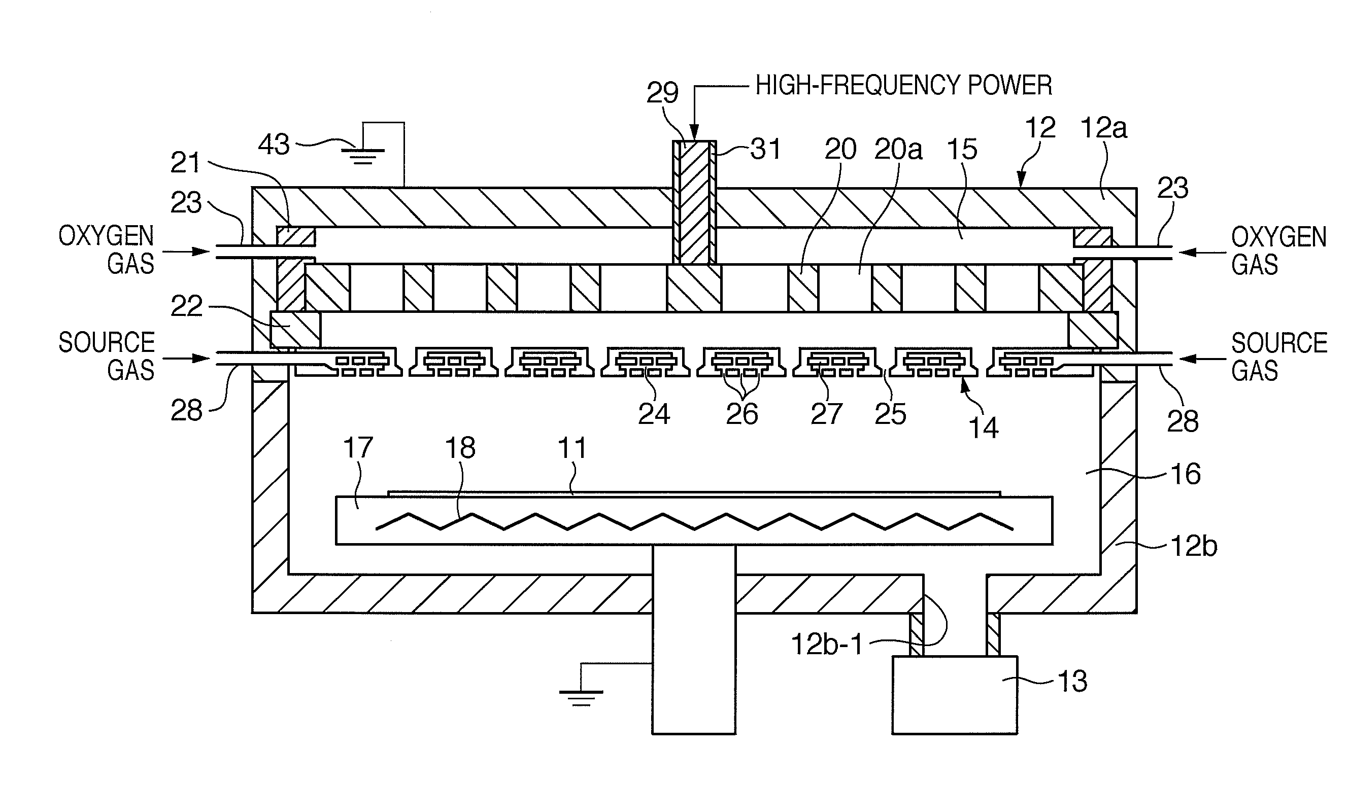
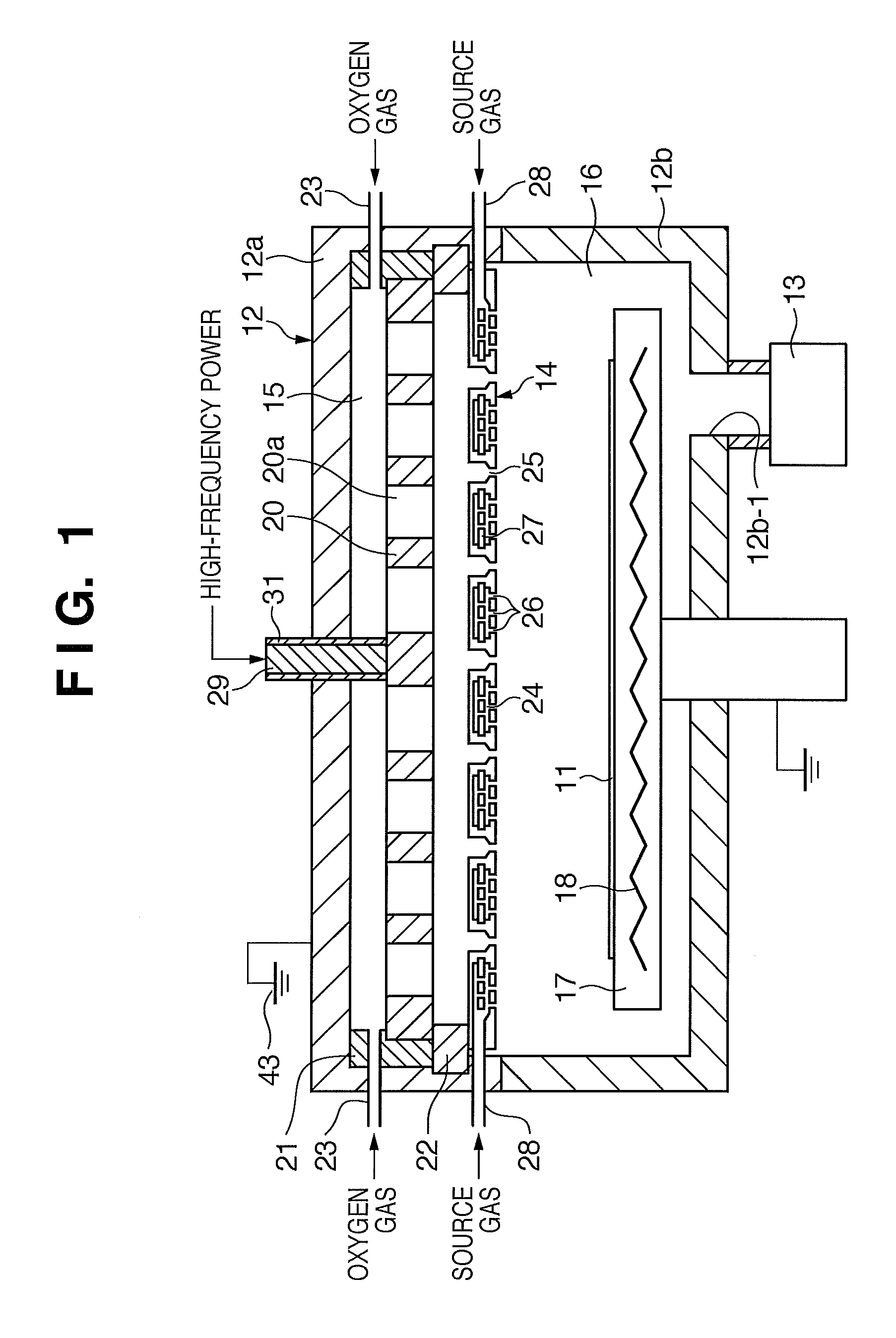
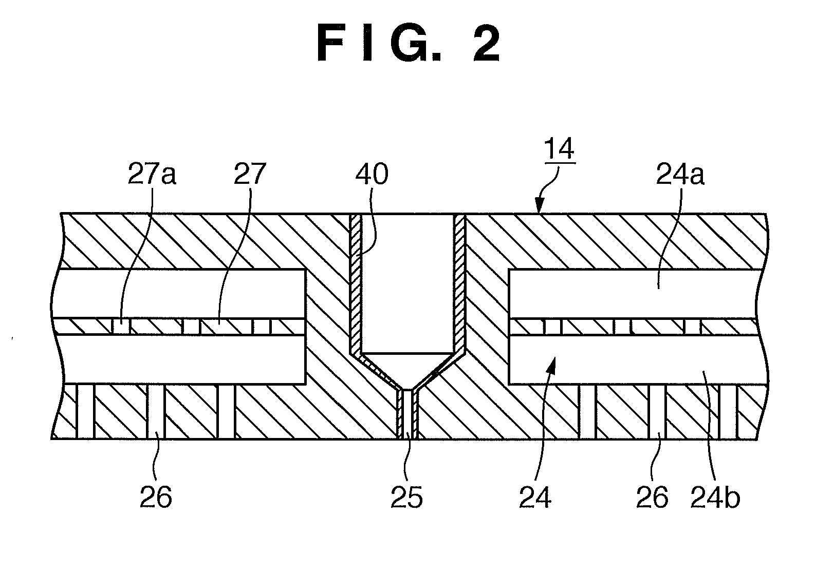
[0036]The first embodiment of the vacuum processing CVD apparatus according to the present invention will be explained below with reference to FIGS. 1 and 2. FIG. 1 is a longitudinal sectional view showing the arrangement of the first embodiment of the CVD apparatus as an example of the vacuum processing apparatus according to the present invention. FIG. 2 is a partially enlarged sectional view showing the internal structure of a partition.
[0037]Referring to FIG. 1, this CVD apparatus preferably uses silane as a source gas, and deposits a silicon oxide film as a gate insulating film on the upper surface of a normal TFT glass substrate 11 (to be also simply referred to as a “glass substrate 11” hereinafter). A vac...
example 1
[0057]An example of the present invention will be explained below.
[0058]In this example, the radical passing amounts were measured by using quartz (SiO2), borosilicate glass, and a fluorine resin as covering materials.
[0059]The SiO2 cover can be formed by forming a coating film of an organic solvent solution of polysilazane, and oxidizing the film. For example, the SiO2 cover can be formed by forming a coating film of a xylene solution of perhydropolysilazane, and naturally oxidizing the film. In this example, the SiO2 cover was formed by forming a coating film of a xylene solution of low-temperature-curing perhydropolysilazane (manufactured by Exousia (QGC-TOKYO)), and heating the processing chamber at 140° C. to 300° C. for about 3 hrs. The thickness was about 1 μm. The SiO2 cover formed on portions other than the through holes 25 was mechanically removed.
[0060]Note that the SiO2 cover can also be formed by another method. For example, it is also possible to use porous SiO2 formed...
second embodiment
[0069]The second embodiment of the CVD apparatus as an example of the vacuum processing apparatus according to the present invention will be explained below with reference to FIG. 3. FIG. 3 is a longitudinal sectional view showing the arrangement of the second embodiment of the CVD apparatus as an example of the vacuum processing apparatus according to the present invention.
[0070]In FIG. 3, the same reference numerals as in FIG. 1 denote practically the same elements as those explained with reference to FIG. 1, and a detailed explanation will not be repeated. The characteristic arrangement of this embodiment is that a disk-like insulating member 33 is formed inside the ceiling of an upper vessel 12a, and an electrode 20 is installed below the insulating member 33. The electrode 20 has no holes 20a described above, and has the form of a single plate. The electrode 20 and a partition 14 form a plasma generating space 15 having a parallel plate electrode structure. The rest of the arra...
PUM
| Property | Measurement | Unit |
|---|---|---|
| Volumetric flow rate | aaaaa | aaaaa |
| Volumetric flow rate | aaaaa | aaaaa |
| Volumetric flow rate | aaaaa | aaaaa |
Abstract
Description
Claims
Application Information