
Transverse oven and method of baking workpieces

a technology of manufacturing ovens and workpieces, which is applied in the direction of muffle furnaces, drying machines with progressive movements, furnaces, etc., can solve the problems of inefficient use of floor space, inability to achieve the flexibility needed to focus heat, and conventional one-size-fits-all configurations. achieve the effect of facilitating transverse baking, reducing operating costs, and increasing the overall width of the oven

Inactive Publication Date: 2010-02-18
GM GLOBAL TECH OPERATIONS LLC
View PDF6 Cites 10 Cited by
  • Summary
  • Abstract
  • Description
  • Claims
  • Application Information

AI Technical Summary

Benefits of technology

The present invention provides a more compact manufacturing oven layout that allows for transverse baking and addresses concerns related to operating costs and floor space. The oven utilizes a combination of radiant and convection heating to treat workpieces more effectively. The oven is designed to allow the workpiece to enter, pass through, and exit the space, when the first and second axes define an angle greater than zero and up to ninety degrees. The method includes rotating the workpiece to a transverse orientation and treating it with convection and radiant heating during different periods to reach a target temperature range. The workpiece exits from the oven in the transverse orientation and rotates back to the longitudinal orientation to continue the work-in-progress. The present invention offers improvements and advantages over the prior art.

Problems solved by technology

For example, the longitudinal orientation of conventional ovens works well for heating most vehicle body types but does not make efficient use of floor space.
Irrespective of the mode of heating, however, another concern is the radial positioning of heat sources, which often results in inadequate heating of the workpieces near the lateral centerline of the oven.
Moreover, conventional one-size fits all configurations do not enable the flexibility needed to focus heat where most needed.

Method used


Image

  • Transverse oven and method of baking workpieces
  • Transverse oven and method of baking workpieces
  • Transverse oven and method of baking workpieces

Examples


Embodiment Construction

).

BRIEF DESCRIPTION OF THE DRAWINGS

[0009]Preferred embodiments of the invention are described in detail below with reference to the attached drawing figures, wherein:

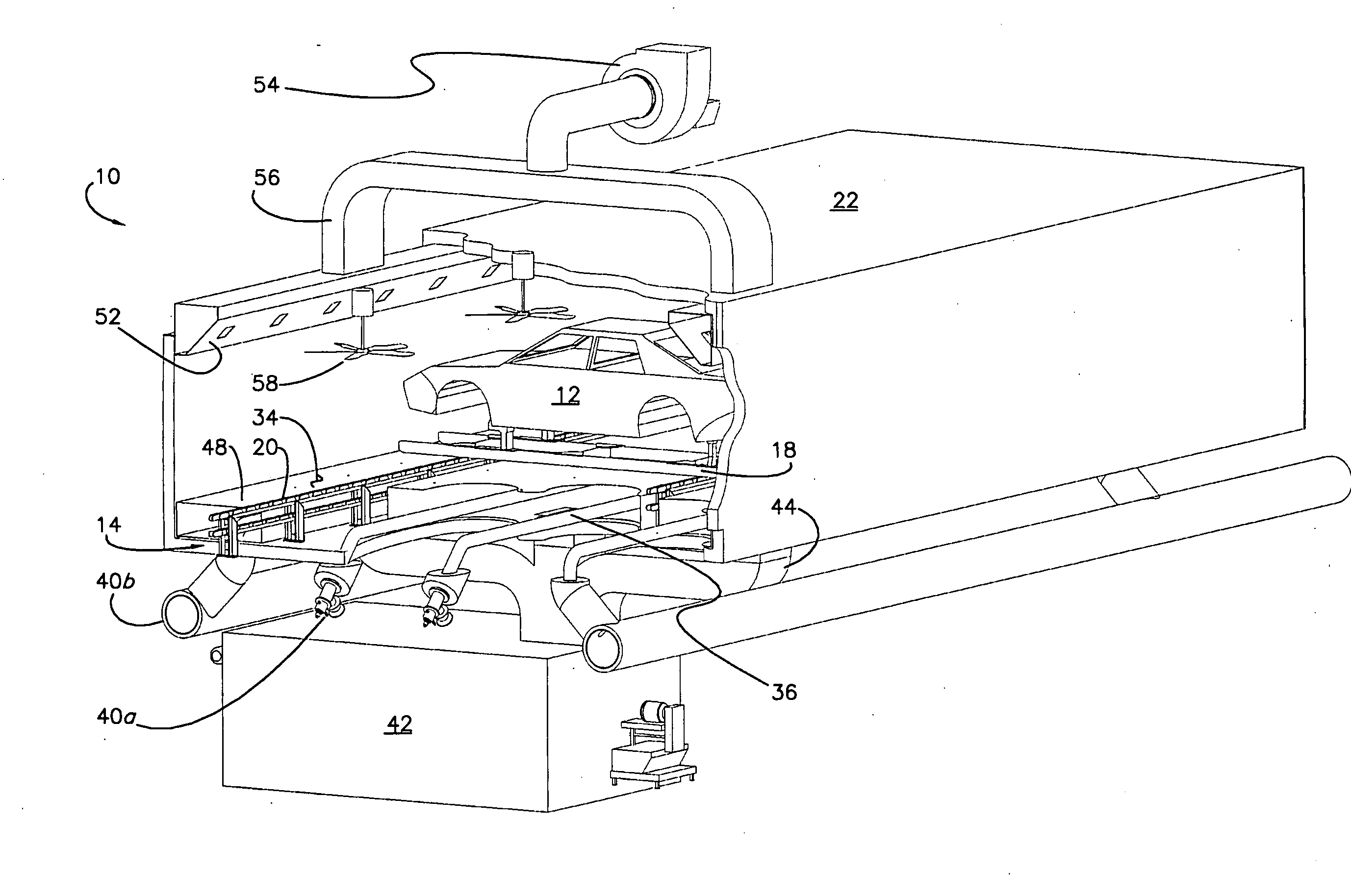
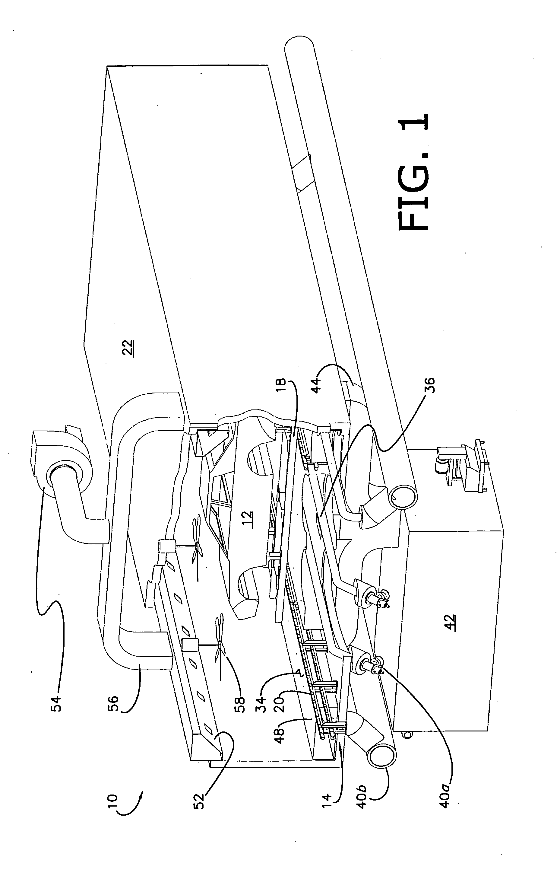
[0010]FIG. 1 is a perspective view of a conveyed vehicle body workpiece being baked inside of a transverse oven including a housing chamber, a high emissivity false floor within the chamber, radiant heating tubes having a generated flame therein and low emissivity reflectors located beneath the floor, ceiling fans, and an exhaust system, a fresh air heater exterior to the chamber, in accordance with a preferred embodiment of the invention;

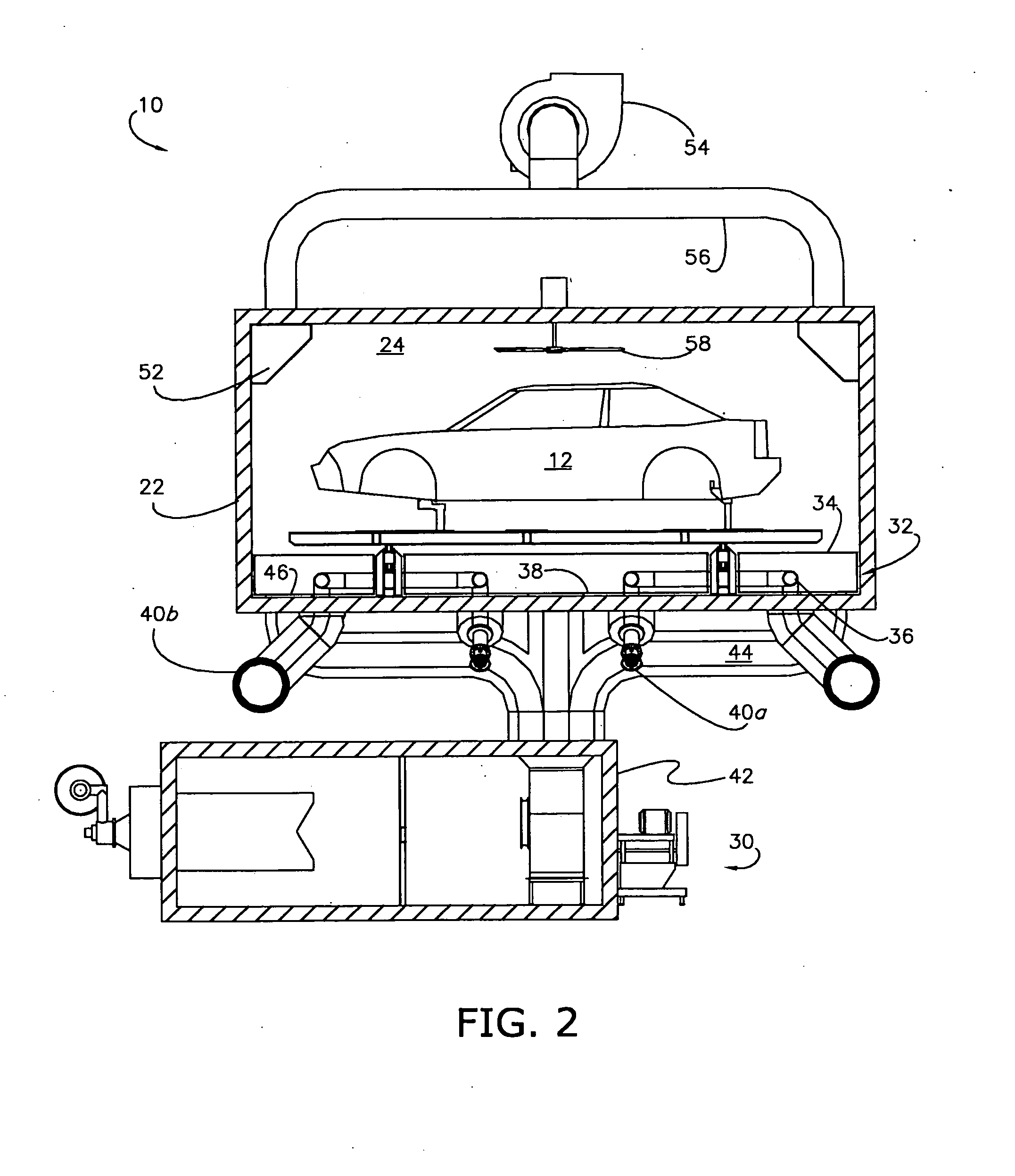
[0011]FIG. 2 is a cross-sectional elevation view of the workpiece and oven shown in FIG. 1;

[0012]FIG. 3 is a longitudinal side elevation view of the oven shown in FIG. 1 treating a plurality of workpieces;

[0013]FIG. 4 is a planar view of a radiant heating tube configuration (in bifurcated layout), in accordance with a preferred embodiment of the invention; and

[0014]FIG. 5 is a plan vie...


PUM


Abstract

A manufacturing oven for and a method of baking a workpiece presenting a transverse orientation relative to the oven, includes dual radiant and convection heating sources operable to uniformly heat the workpiece by focusing convection heating air towards desirous parts of the workpiece, and preferably includes a chamber, a high emissivity false floor, at least one radiant heating element beneath the floor, at least one reflector beneath each element and configured to redirect radiant heat energy towards the floor, a fresh air heater for delivering fresh heated air into the chamber, an exhaust system for removing heated air and evaporated paint solvents from the chamber, and at least one ceiling fan operable to cause lighter heated air to flow from the ceiling of the chamber and towards the workpiece.

Description

BACKGROUND[0001]The present invention relates to manufacturing ovens and methods of baking workpieces, and more particularly, to an oven presenting, and a method of baking workpieces utilizing, dimensions suitable for transverse baking, and / or a more uniform heating configuration having dual heat sources.BACKGROUND OF THE INVENTION[0002]Manufacturing ovens are used to bake workpieces to specified temperature ranges as part of many curing processes. In automotive settings, for example, recently painted workpieces have long been conveyed longitudinally into an elongated oven that typically features radiant heat sources located along the outside perimeter of a chamber. Though widely utilized, various concerns are appreciated in the art. For example, the longitudinal orientation of conventional ovens works well for heating most vehicle body types but does not make efficient use of floor space. Where space is limited, some conventional ovens present a “U”-shaped layout that requires larg...

Claims


Application Information

Patent Timeline
Patent Type & Authority Applications(United States)
IPC IPC(8): F27B9/06F27D11/00
CPCF26B3/343F26B15/14F27B9/068F27B9/06F26B2210/12
Inventor SCHWARTZ, GLEN N.CLAYA, JOSEPH E.
Owner GM GLOBAL TECH OPERATIONS LLC
Learn More