Electro-optical device, method of driving the same, and electronic apparatus

Active Publication Date: 2010-02-18
BOE TECH GRP CO LTD
View PDF11 Cites 6 Cited by
  • Summary
  • Abstract
  • Description
  • Claims
  • Application Information

AI Technical Summary

Benefits of technology

[0020]According to this invention, the length of one sub-field is adjusted and the intensity of the light incident on the pixel is controlled even if the response time of the electro-optical element changes in response to the temperature, thereby making it possible to keep the display luminance constant even if the temperature changes. Specifically, if the response time becomes longer in response to the temperature, it is possible to make the temporal alteration in the transmittance constant by making shorter the length of one sub-field even if the temperature changes. The sub-field is one unit that can control the lighting and/or the turning off of the pixel. However, if the length of the sub-fiel

Problems solved by technology

For this reason, even though a grayscale corresponding to a value of digital data can be accurately minced at a certain temperature, the grayscale that has to be displayed becomes inaccurate if the temperature changes.
However, if the length of the sub-field changes, the length of the residual period changes during which it is not possible to control the lighting and/or

Method used


Image

  • Electro-optical device, method of driving the same, and electronic apparatus
  • Electro-optical device, method of driving the same, and electronic apparatus
  • Electro-optical device, method of driving the same, and electronic apparatus

Examples


Example

[0036]A liquid crystal display 1 according to an embodiment of the invention includes a crystal display panel as a main portion. The crystal display panel is constituted in such a manner that the electrode forming surfaces of an element substrate and an opposite substrate, on which a thin film transistor (hereinafter, referred to as “TFT”) are formed as a switching element, face each other, and are adhered so that a uniform gap is maintained, with liquid crystals being interposed in the gap.

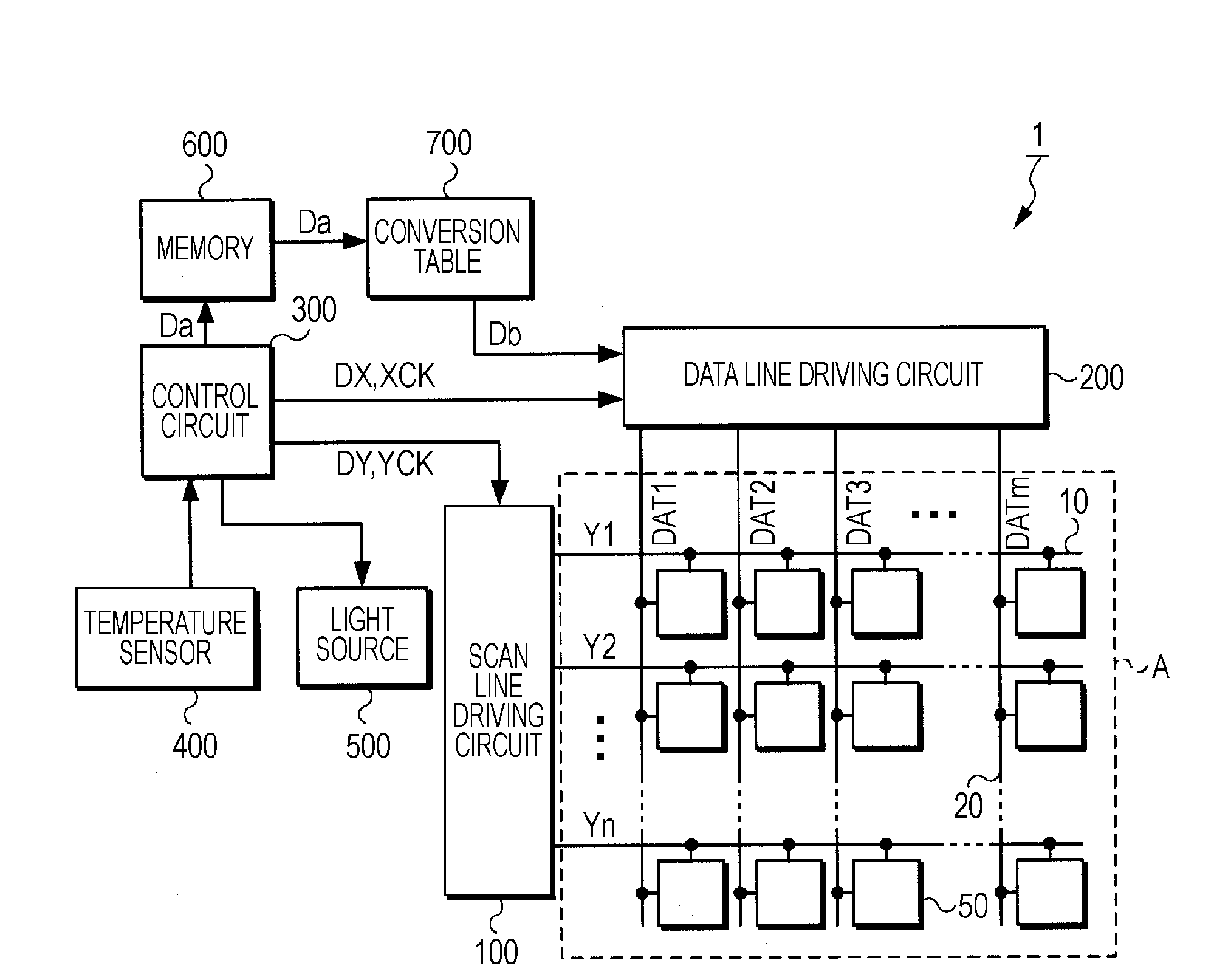
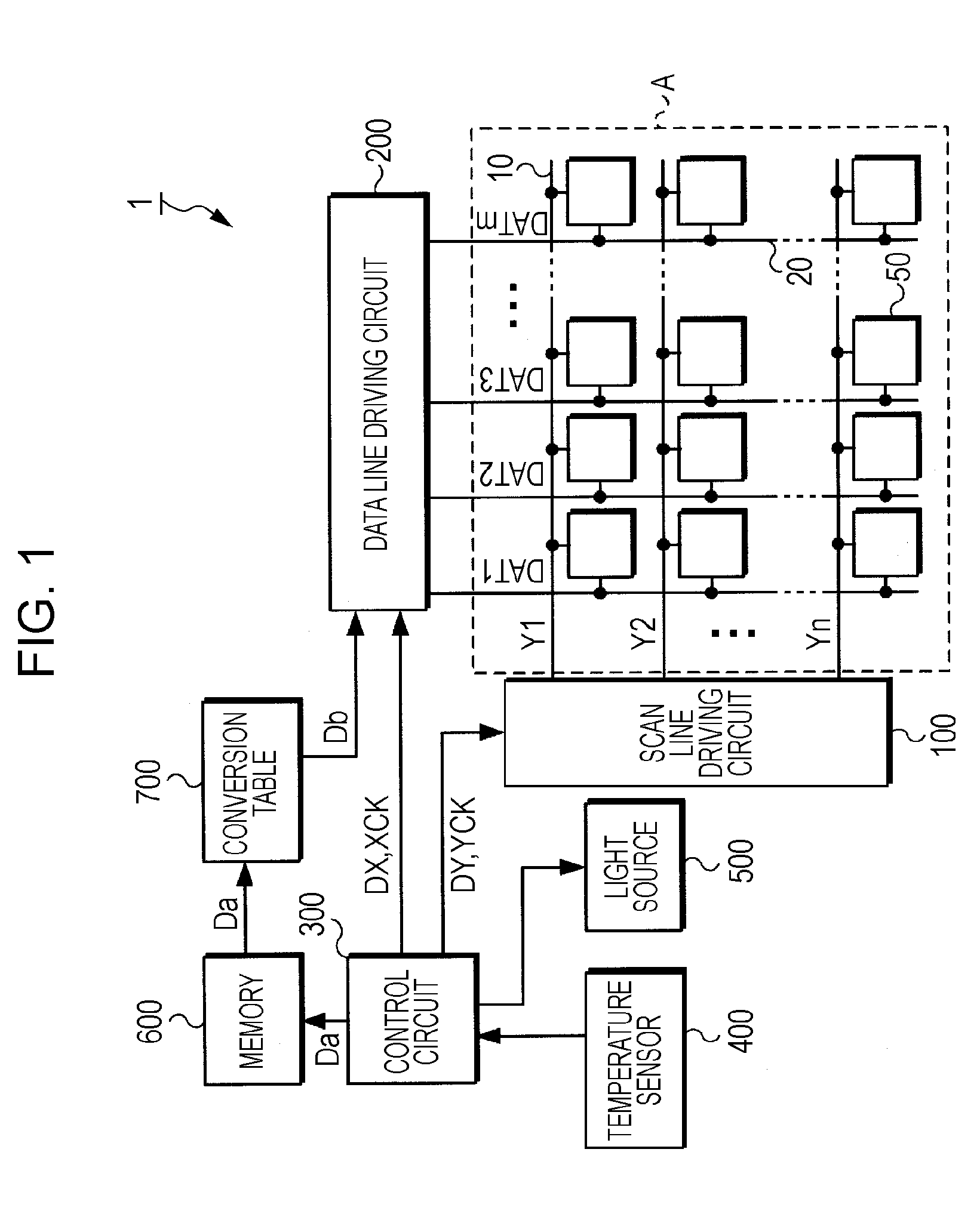
[0037]FIG. 1 is a block diagram showing the entire configuration of the liquid crystal display 1. The liquid crystal display 1 includes a scan line driving circuit 100, a data line driving circuit 200, a control circuit 300, a temperature sensor 400, a light source 500, a memory 600, a conversion table 700, and an image display region A. Among these constituents, the liquid crystal panel includes at least the image display region A. The light source 500 is constituted as external circuitry of the...


PUM


Abstract

An electro-optical device includes a pixel that has an electro-optical element with a light transmittance that changes to a predetermined value in response to an applied voltage, which changes in response to the temperature. A light source irradiates light to the pixel. A driving unit includes a predetermined number of sub-fields having the same length in one frame. The driving unit provides either an on-voltage indicating light-on or an off-voltage indicating light-off to the pixel in each of the predetermined number of the sub-fields in response to the grayscale to be displayed. A temperature measuring unit measures the temperature and outputs a temperature signal. A time controlling unit controls the length of one sub-field on the basis of the temperature signal. A light intensity controlling unit controls the intensity of the light incident on the pixel on the basis of the temperature signal.

Description

BACKGROUND[0001]1. Technical Field[0002]The present invention relates to an electro-optical device using an electro-optical material such as a liquid crystal, a method of driving the same, and an electronic apparatus.[0003]2. Related Art[0004]A liquid crystal is known as an electro-optical material that has optical characteristics that are changed by electrical energy. The liquid crystal has transmittance that changes in response to an applied voltage. Liquid crystal devices using the change in transmittance are known. Liquid crystal devices include a plurality of scan lines, a plurality of data lines, and a plurality of pixels provided to correspond to intersections of the scan lines and the data lines. The plurality of pixels has a pixel electrode, an opposite electrode, and a liquid crystal element composed of the liquid crystal which is interposed therebetween.[0005]As a method of digitally driving liquid crystal devices, there is known a sub-field driving method that divides on...

Claims


Application Information

Patent Timeline
IPC IPC(8): G09G5/02G09G3/36
CPCG02F1/1362G02F2203/30G02F2203/60G09G2320/041G09G3/2025G09G3/3648G09G3/2014
Inventor OKUYAMA, TOMOYUKIMATSUMOTO, TETSURO
Owner BOE TECH GRP CO LTD
Why Eureka
Try Eureka