Large bore pet and hybrid pet/ct scanners and radiation therapy planning using same

a technology of ct scanner and large bore pet, which is applied in the field of large bore pet scanner and hybrid pet/ct scanner, can solve the problems of affecting the health of the patient, the inability to accurately replicate the anatomical configuration during therapy, and the inability to achieve the combination of large patient aperture and high sensitivity, so as to reduce the radially inward extent, the effect of fast response speed and reduced radially inward exten

Active Publication Date: 2010-02-18
KONINKLIJKE PHILIPS ELECTRONICS NV
View PDF4 Cites 78 Cited by
  • Summary
  • Abstract
  • Description
  • Claims
  • Application Information

AI Technical Summary

Benefits of technology

[0023]In accordance with another disclosed aspect, an imaging system is disclosed for imaging a human subject, the imaging system comprising a ring of positron emission tomography (PET) detectors having no side shielding or side shielding of reduced radially inward extent. The ring of PET detectors has a fast response speed effective to enable a narrow coincidence time window for identifying substantially coincident 511 keV detection events, which narrow coincidence time window compensates for additional noise introduced by the lack of side shielding or by the side shielding of reduced radially inward extent.

Problems solved by technology

The typically high tissue growth rate and “unnatural” nature of the malignant tissue results in the ionizing radiation preferentially damaging or killing the malignant tissue; however, healthy tissue is also adversely impacted by the ionizing radiation.
As a result, if the patient has to assume a different position in the CT scanner than in the radiation therapy system due to a smaller patient aperture of the former, then the anatomical images used for therapy planning may not accurately replicate the anatomical configuration during therapy.
A substantial obstacle to utilizing PET in radiation therapy planning and therapy monitoring is that PET scanners do not have the requisite combination of large patient aperture and high sensitivity.
The radiopharmaceutical dosage is strictly limited due to safety concerns.
The imaged volume increases with the square of the scanner diameter, which complicates scaling up the geometry to larger size (for example, to an 85 cm patient aperture).
Stabilization of the patient in the PET scanner is another issue, especially in some hybrid CT / PET scanners in which the patient is supported by cantilevering in the PET gantry.
The brain and bladder are therefore substantial sources of stray radiation that can lead to false gamma ray counts that degrade image quality.
Use of energy-range and time-range filtering reduces these stray counts; however, in human-sized PET scanners these post-acquisition filtering techniques have been found to be insufficient, by themselves, to obtain clinical quality images for oncological applications.
A patient aperture of 70 cm is large enough to receive a human subject, but is too small for performing imaging of a human subject in the same position as the subject would assume in the radiation therapy system.
For example, Mullani, U.S. Pat. No. 4,559,597 issued in 1985 discloses time-of-flight PET and considers the possibility of operating without side shields (called “septa” in Mullani), but concludes that omitting side shields introduces a substantial amount of scatter in the data and may not be acceptable for a clinically usable system.
Other issues with oncological PET relate to scan time and patient inconvenience.
However, this arrangement results in cantilevered support of the patient in the PET scanner, with the possible consequence of downward deflection of the patient support and resultant PET / CT image misalignment.
However, the correction increases computational complexity, and introduces yet another potential source of error in fusing CT and PET images for radiation therapy planning.

Method used


Image

  • Large bore pet and hybrid pet/ct scanners and radiation therapy planning using same
  • Large bore pet and hybrid pet/ct scanners and radiation therapy planning using same
  • Large bore pet and hybrid pet/ct scanners and radiation therapy planning using same

Examples


Embodiment Construction

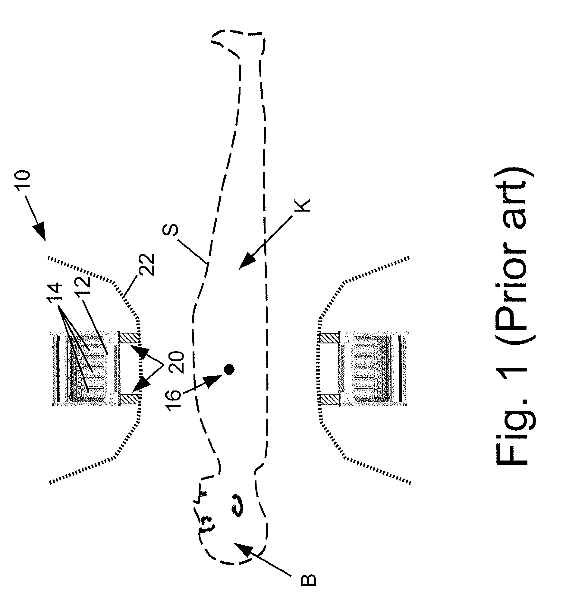
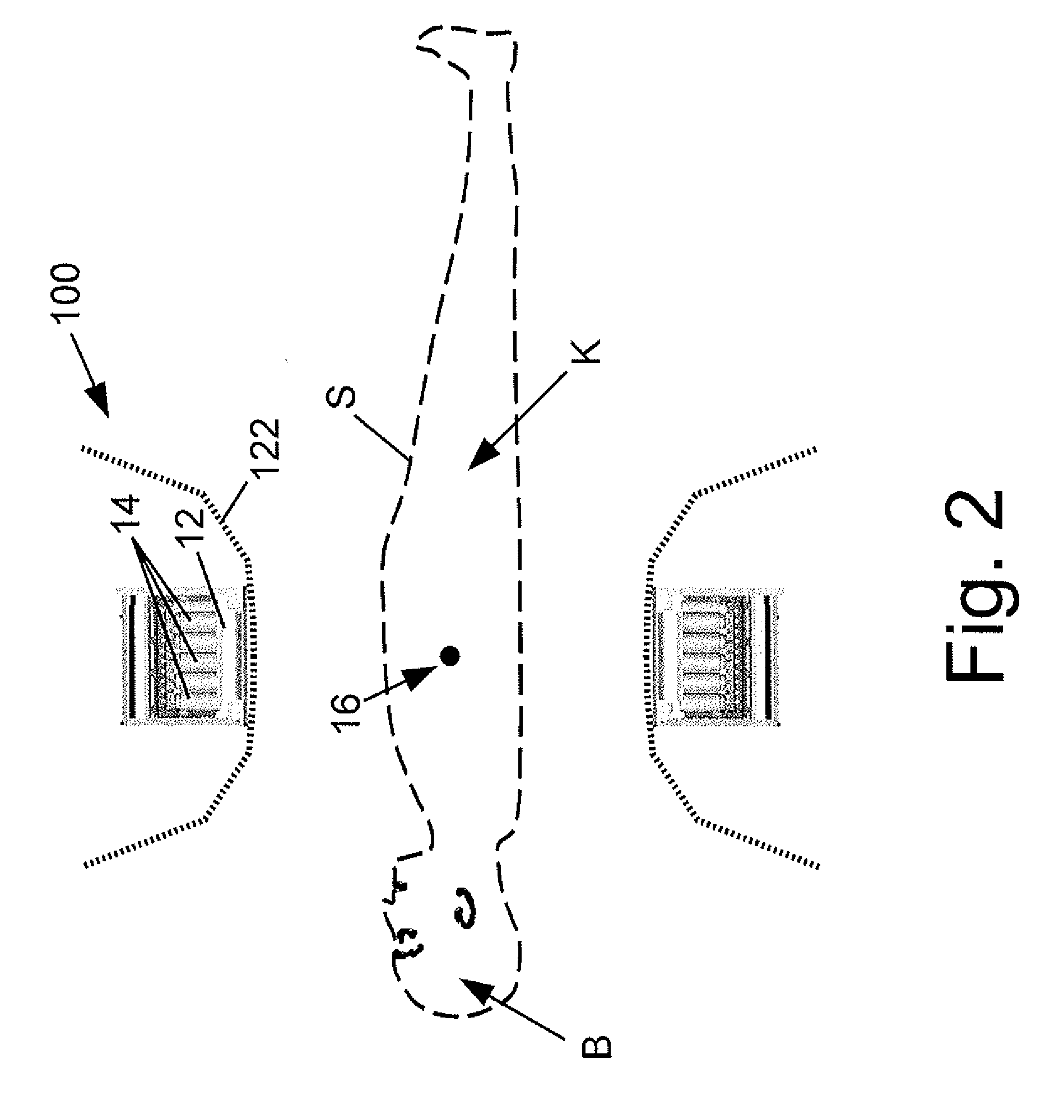
[0028]With reference to FIG. 2, a detector ring 100 is similar to the detector ring 10 of FIG. 1. The detector ring 100 includes the scintillator ring 12 viewed by photomultiplier tube (PMT) detectors 14. The patient S is arranged with a tumor or other malignancy of interest positioned at the isocenter 16 of the detector ring 100. However, the detector ring 100 omits the side shield rings 20 of the PET scanner of FIG. 1. As a result, a modified PET housing 122 has a larger patient aperture than the housing 22 of the conventional detector ring 10 of FIG. 1. For example, the scintillator ring 12 of the Gemini™ Time-of-Flight PET / CT scanner (available from Koninklijke Philips Electronics N.V., Eindhoven, the Netherlands) has a detector diameter of 89 cm defined by the scintillator ring 12. However, in the Gemini™ PET scanner, the shield rings 20 extend radially about 10 centimeters inward, so that the shield rings 20 have an inner diameter of 70 cm. As a result, the exterior housing 22...


PUM


Abstract

An imaging system comprises: a ring of positron emission tomography (PET) detectors; a PET housing at least partially surrounding the ring of PET detectors and defining a patient aperture of at least 80 cm; a coincidence detection processor or circuitry configured to identify substantially simultaneous 511 keV radiation detection events corresponding to electron-positron annihilation events; and a PET reconstruction processor configured to reconstruct into a PET image the identified substantially simultaneous 511 keV radiation detection events based on lines of response defined by the substantially simultaneous 511 keV radiation detection events. Radiation planning utilizing such an imaging system comprises: acquiring PET imaging data for a human subject arranged in a radiation therapy position requiring a patient aperture of at least about 80 cm; reconstructing said imaging data into a PET image encompassing an anatomical region to undergo radiation therapy; and generating a radiation therapy plan based on at least the PET image.

Description

CROSS REFERENCE TO RELATED APPLICATIONS[0001]This application claims the benefit of U.S. provisional application Ser. No. 61 / 089,193 filed Aug. 15, 2008, which is incorporated herein by reference.BACKGROUND[0002]The following relates to the oncological arts, medical imaging arts, positron emission tomography (PET) arts, and related arts.[0003]Radiation therapy has been shown to be effective in treating certain types of cancer. In these techniques, a high dosage of ionizing radiation is applied to the tumor or other malignant tissue. The typically high tissue growth rate and “unnatural” nature of the malignant tissue results in the ionizing radiation preferentially damaging or killing the malignant tissue; however, healthy tissue is also adversely impacted by the ionizing radiation. Accordingly, the ionizing radiation is applied in a tomographic or multi-beam configuration with the beam intensities and, optionally, cross-sectional beam profiles designed to deliver a therapeutic radia...

Claims


Application Information

Patent Timeline
Patent Type & Authority Applications(United States)
IPC IPC(8): A61N5/10G21K7/00A61B6/04
CPCA61N2005/1052A61N2005/1061A61B6/032A61B6/037A61N5/103G01T1/2985A61B6/5235A61N5/1039
Inventor MANIAWSKI, PIOTR J.GAGNON, DANIEL
Owner KONINKLIJKE PHILIPS ELECTRONICS NV
Why Eureka
Try Eureka