Method for Manufacturing Surface Acoustic Wave Apparatus

Inactive Publication Date: 2010-02-25
KYOCERA CORP
View PDF9 Cites 66 Cited by
  • Summary
  • Abstract
  • Description
  • Claims
  • Application Information

AI Technical Summary

Benefits of technology

[0035]In accordance with the thirteenth aspect, a large number of WLP-type surface acoustic wave apparatuses can be simultaneousl

Problems solved by technology

Moreover, many processes are required in the manufacturing process for forming t

Method used


Image

  • Method for Manufacturing Surface Acoustic Wave Apparatus
  • Method for Manufacturing Surface Acoustic Wave Apparatus
  • Method for Manufacturing Surface Acoustic Wave Apparatus

Examples


first embodiment

[0045]A first embodiment relates to a method for manufacturing a surface acoustic wave apparatus.

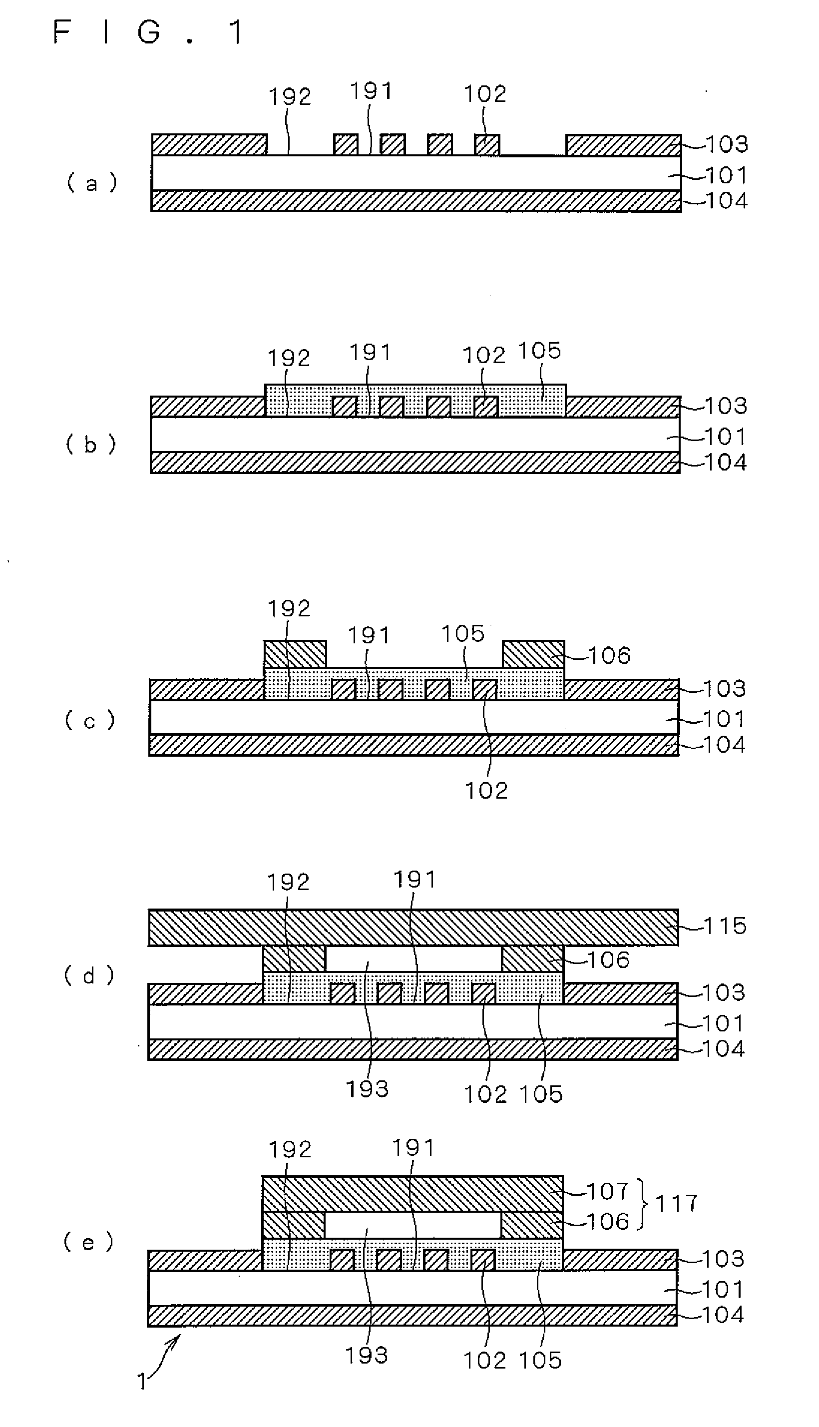
[0046]FIG. 1 is a view describing a method for manufacturing a surface acoustic wave apparatus in accordance with the first embodiment. FIGS. 1(a) to 1(d) are cross-sectional views of a work in process for a surface acoustic wave apparatus 1, and FIG. 1(e) is a cross-sectional view of the surface acoustic wave apparatus 1. FIGS. 1(a) to 1(e) are schematic views that help to improve understanding of the positional relationship among the respective parts of the work in process for the surface acoustic wave apparatus 1, or the surface acoustic wave apparatus 1.

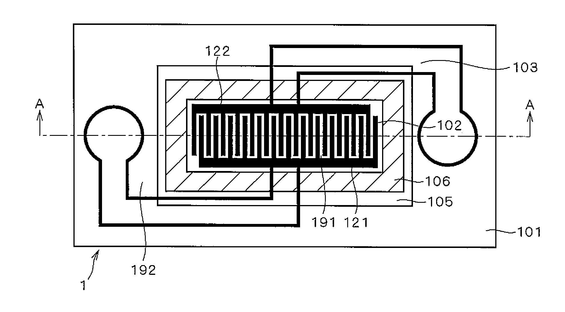
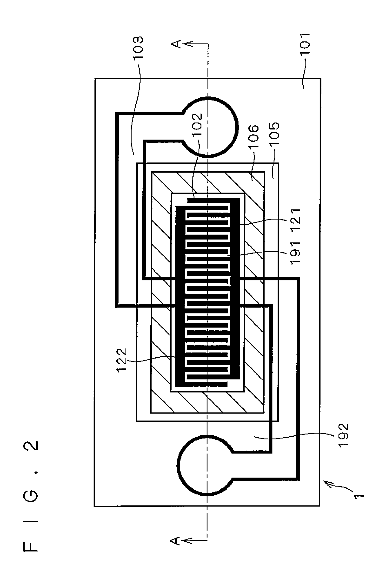
[0047]As shown in FIG. 1(e), the surface acoustic wave apparatus 1 to be manufactured by the method for manufacturing a surface acoustic wave apparatus in accordance with the first embodiment is configured by a piezoelectric substrate 101, an IDT (InterDigital Transducer) electrode 102 and a connection line 103, formed on an upper sur...

second embodiment

[0091]A second embodiment relates to a frame-member forming process that can be adopted in place of the frame-member forming process of the method for manufacturing a surface acoustic wave apparatus of the first embodiment.

[0092]FIG. 3 is a view describing a frame-member forming process in accordance with the second embodiment. FIGS. 3(a) and 3(b) are cross-sectional views of a work in process of the surface acoustic wave apparatus 1. FIGS. 3(a) and 3(b) are schematic views that help to improve understanding of the positional relationship among the respective parts of the work in process for the surface acoustic wave apparatus 1.

[0093]In the frame-forming process of the second embodiment, a film-shaped molded body is used as a film made of a first resist. That is, first, as shown in FIG. 3(a), a first film 219 made from the first resist is mounted on a piezoelectric substrate 101. Thereafter, as shown in FIG. 3(b), the first film 219 is patterned by a photolithography method, and th...

third embodiment

[0096]A third embodiment relates to a lid-member forming process that can be adopted in place of the lid-member forming process of the method for manufacturing a surface acoustic wave apparatus of the first embodiment.

[0097]FIGS. 4(a) to 4(d) are views describing a lid-member forming process in accordance with the third embodiment. FIGS. 4(a) to 4(c) are cross-sectional views of a work in process of the surface acoustic wave apparatus 1, and FIG. 4(d) is a cross-sectional view of the surface acoustic wave apparatus 1. FIGS. 4(a) to 4(d) are schematic views that help to improve understanding of the positional relationship among the respective parts of the work in process for the surface acoustic wave apparatus 1 or of the surface acoustic wave apparatus 1.

[0098]As shown in FIG. 4(a), the second film 315 to be used for the lid-member forming process of the third embodiment is formed by laminating two layers, that is, a resin layer 315a and a holding layer 315b having a higher Young's ...


PUM


Abstract

Provided is a method for manufacturing a surface acoustic wave apparatus that can reduce degradation of electric characteristics and also reduce the number of manufacturing processes. The method for manufacturing a surface acoustic wave apparatus includes the steps of: forming an IDT electrode on an upper surface of a piezoelectric substrate, forming a frame member surrounding a formation area in which the IDT electrode is formed on the piezoelectric substrate, and mounting a film-shaped lid member on the upper surface of the frame member so as to be joined to the frame member so that a protective cover, used for covering the formation area and for providing a tightly-closed space between it and the formation area, is formed.

Description

TECHNICAL FIELD[0001]The present invention relates to a method for manufacturing a surface acoustic wave apparatus mainly used for a radio communication circuit of a mobile communication apparatus or the like and, more specifically, to a method for manufacturing a surface acoustic wave apparatus by which a surface acoustic wave apparatus capable of being surface-packaged can be miniaturized and can be formed into a packaged state by using wafer processes.BACKGROUND ART[0002]In recent years, with respect to portable terminal devices used for mobile communication, small-size and light-weight devices have been developed, and in order to achieve devices having multiple bands required for a plurality of communication systems and portable terminal devices with multiple functions, the number of built-in circuits has been increased. For this reason, in order to improve packaging density, there have been strong demands for miniaturizing the electronic parts to be used therein into small-size...

Claims


Application Information

Patent Timeline
IPC IPC(8): H01L41/22
CPCH03H9/059H03H9/1092H03H9/0576H03H9/14582Y10T29/42H03H3/08H05K3/3426H01L41/23H01L41/27H05K1/144H03H9/008H01L2224/11H01L2224/94H01L2924/16235Y10T29/49005Y10T29/49144Y10T29/49155H03H9/1071H10N30/02H10N30/05H03H3/007H03H2003/0071
Inventor FUKANO, TORU
Owner KYOCERA CORP
Why Eureka
Try Eureka