

Method and system for laser processing
a laser processing and laser technology, applied in laser beam welding equipment, welding equipment, metal-working equipment, etc., can solve the problems of difficult manufacturing of high-power lasers having a good beam quality, limited power of known single-mode fibre lasers to less than 1000 w, and the number of limitations encountered by this procedur
- Summary
- Abstract
- Description
- Claims
- Application Information
AI Technical Summary
Benefits of technology
Problems solved by technology
Method used
Image

Examples
Embodiment Construction
[0012]Object of the invention is to provide a method for laser processing overcoming the above mentioned limitations.
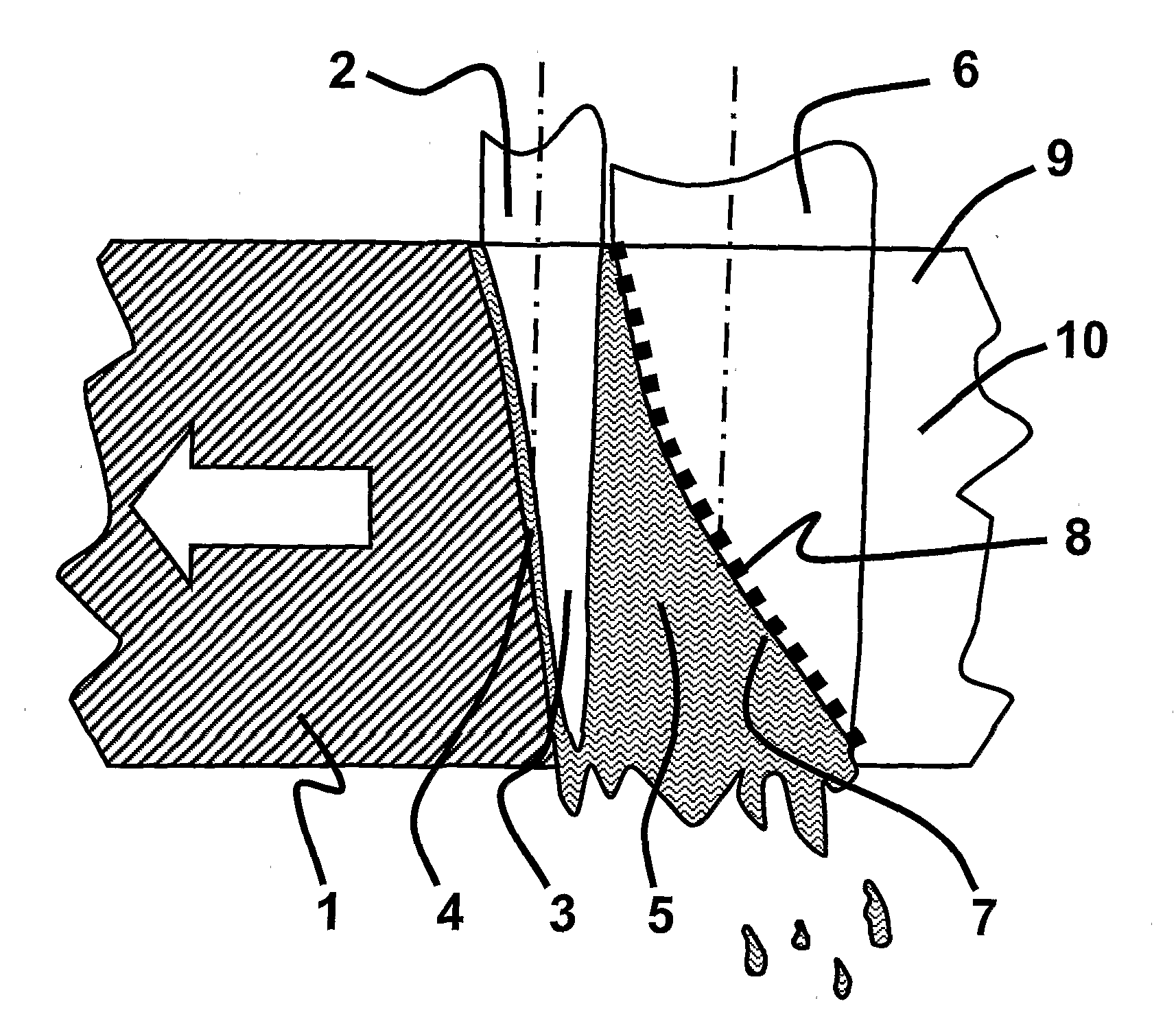
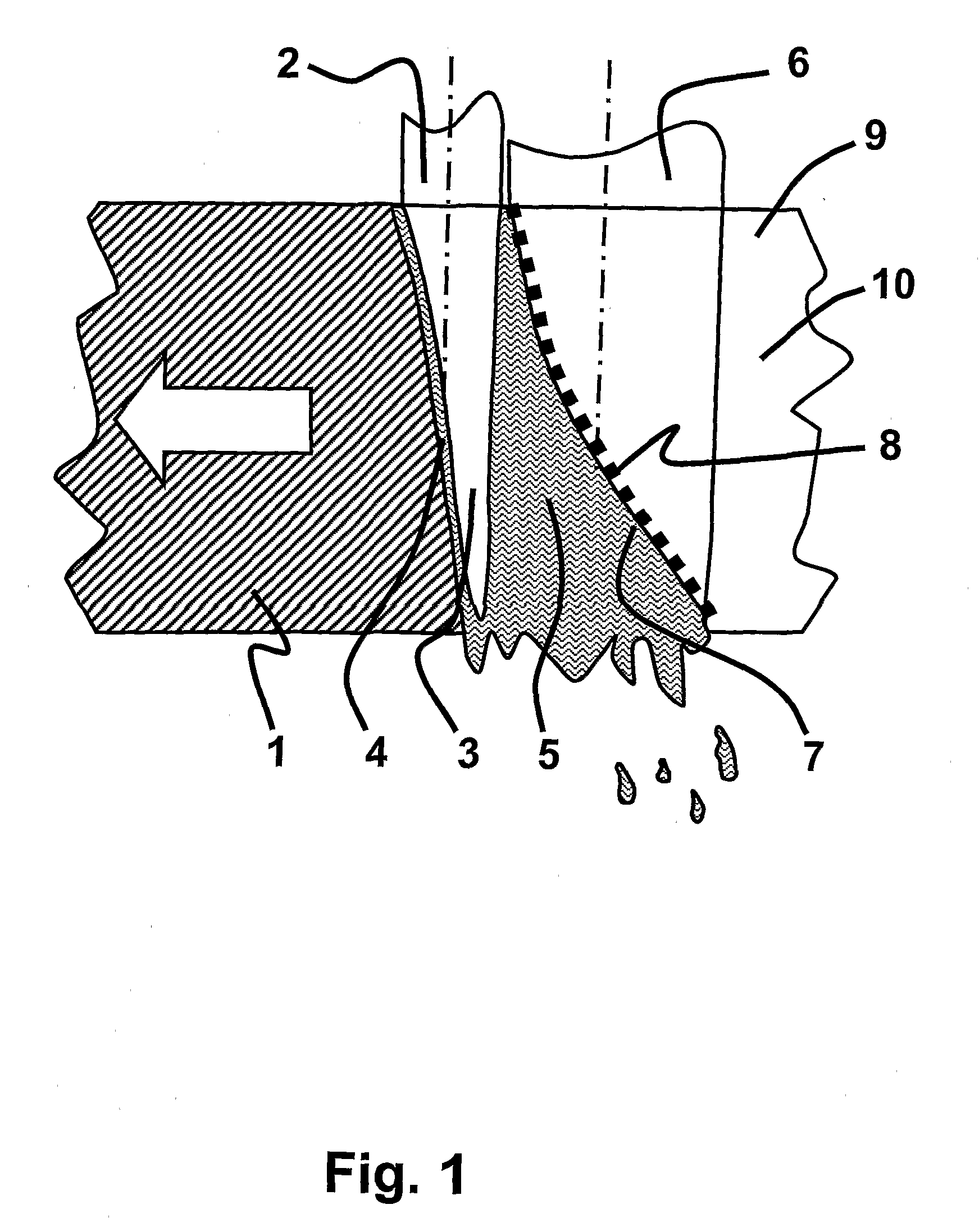
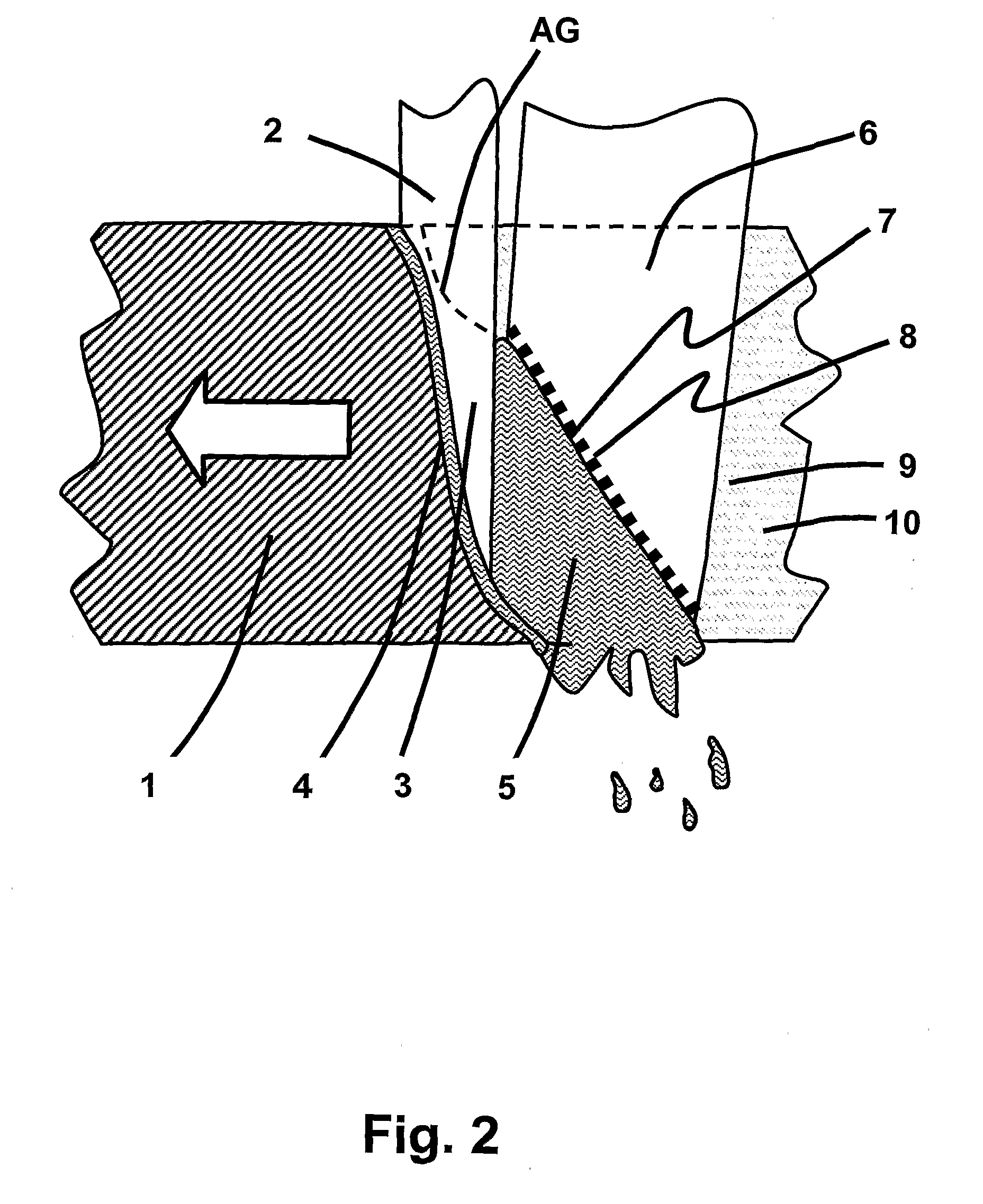
[0013]This is according to the invention obtained by a method for laser processing using multiple laser beams, wherein at least one first laser beam, the so-called melting beam, is coupled into the work piece material to generate a melt and to form a keyhole, and at least one second laser beam, the so-called melt ejection beam, is guided onto selected surface regions of the melt, so as to evaporate material from the melt surface and provide a high pressure in a Knudsen-layer forcing at least part of the melt out of the processing region, thereby forming a kerf having a cut front and sidewalls. The high pressure in the Knudsen layer is preferably provided so as to provide a substantially steady flow of melt out of the processing region.
[0014]For the sake of simplicity the following terms are used to describe the laser process.
[0015]The laser processing is applied to a ...
PUM
| Property | Measurement | Unit |
|---|---|---|
| Length | aaaaa | aaaaa |
| Length | aaaaa | aaaaa |
| Length | aaaaa | aaaaa |
Abstract
Description
Claims
Application Information