Injection molding system, computer program, method of injection molding, and injection molding machine

a technology of injection molding and injection molding machine, which is applied in the field of injection molding system, can solve the problems of mold cavity surface being insufficiently transferred to the molded product, mold defect, weld line or silver streak, etc., and achieves the effect of preventing cooling and solidification of the molded product, long pressure retention time, and effective preventing a molding d

Active Publication Date: 2010-02-25
MITSUBISHI HEAVY INDS PLASTIC TECH
View PDF5 Cites 8 Cited by
  • Summary
  • Abstract
  • Description
  • Claims
  • Application Information

AI Technical Summary

Benefits of technology

[0036]According to the present invention, the temperature control is performed so that the cavity temperature is maintained within the predetermined temperature range after the injection of the resin is started. Thus, even when a long pressure retaining time is taken for a thick molded product or the like, cooling and solidification of the molded product can be prevented to sufficiently apply retaining pressure without sacrificing productivity and energy consumption.
[0037]At this time, supply timing of the heating medium is set so that the mold temperature that is increased by a delay of heat transfer still after the stop of the heating does not exceed an upper limit of the predetermined temperature range, and thus the temperature can be maintained within the predetermined temperature range for a long time, and a long pressure retaining time can be ensured to effectively prevent a molding defect such as a sink mark. The temperature control of the mold is performed only by switching ON / OFF the supply of the heating medium, thereby facilitating the temperature control. The temperature control is performed within the predetermined temperature range, and thus can be efficiently performed without excessive cooling or the like. Further, the mold temperature is always maintained within the predetermined temperature range, and particularly when the molding material is crystalline resin with a low crystallization speed, a sufficient time for crystallization can be obtained, which does not prevent the molecules of the resin from being easily moved unlike the case where the temperature is reduced to a temperature lower than the temperature range, and prevents variations in crystallization quality.
[0038]In the process of cooling the resin, the temperature control is performed so that the mold temperature is maintained within the temperature range effective for resin annealing. Thus, resin annealing can be reliably performed in a series of injection molding cycles. At this time, rapid cooling with the cooling medium can be performed before and after the annealing to shorten the molding cycles.

Problems solved by technology

In this case, a cavity surface of the mold may be insufficiently transferred to a molded product, and a defect referred to as a weld line or a silver streak may occur on a molded product surface.
However, taking a long pressure retaining time for a thick molded product or the like may cause a molding defect such as a sink mark if a temperature of a mold is reduced during pressure retention after completion of injection and cooling and solidification of the molded product proceed.
Also, increasing a heating temperature of the mold to increase the time for pressure retention may increase a cooling time to reduce productivity and waste heating energy consumed.
Further, a low heating temperature of the mold cannot provide a sufficient pressure retaining time.

Method used


Image

  • Injection molding system, computer program, method of injection molding, and injection molding machine
  • Injection molding system, computer program, method of injection molding, and injection molding machine
  • Injection molding system, computer program, method of injection molding, and injection molding machine

Examples


Embodiment Construction

[0062]Now, the present invention will be described in detail for the case of using crystalline resin, which is the most effective, with reference to an embodiment shown in the accompanying drawings.

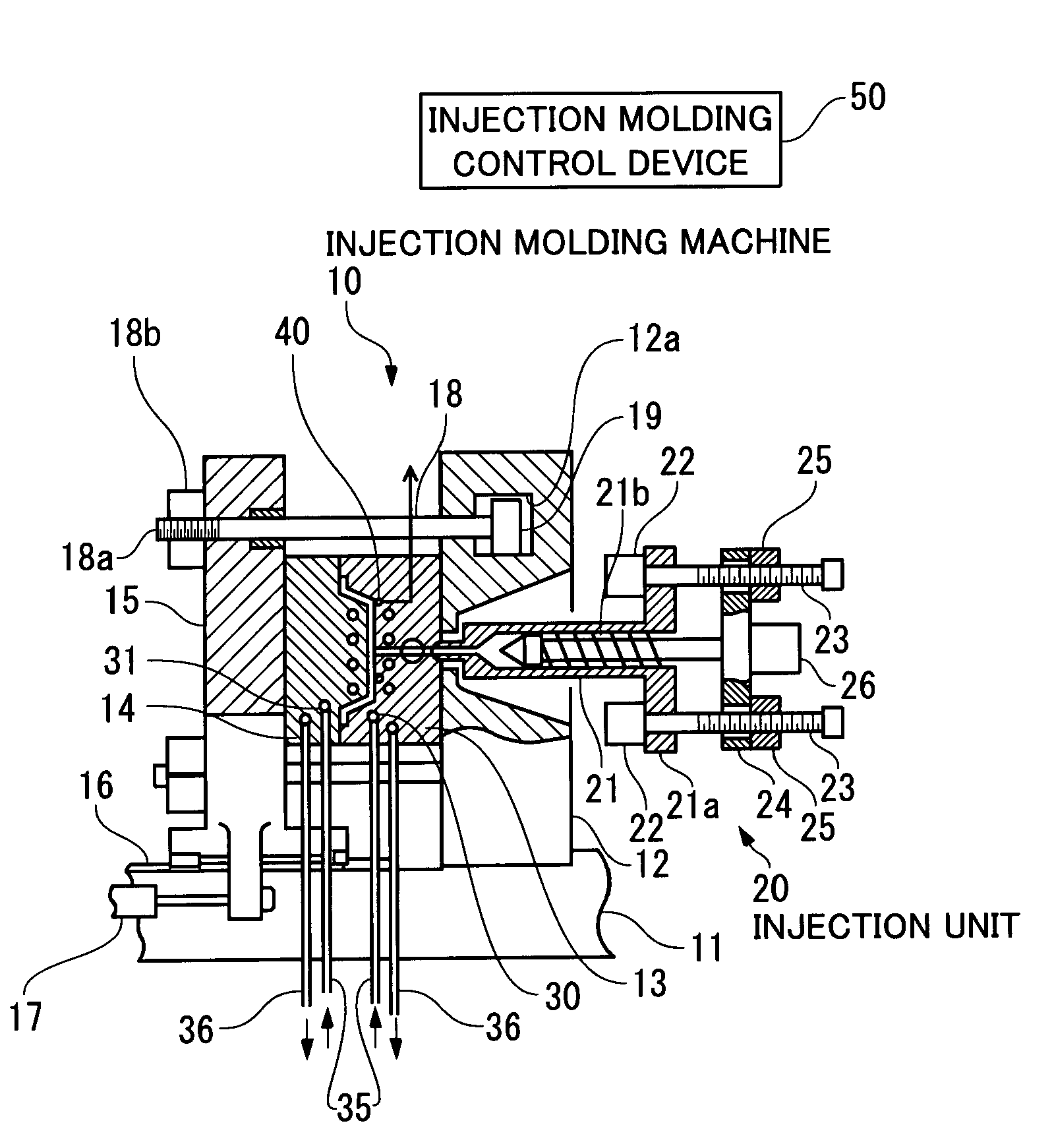
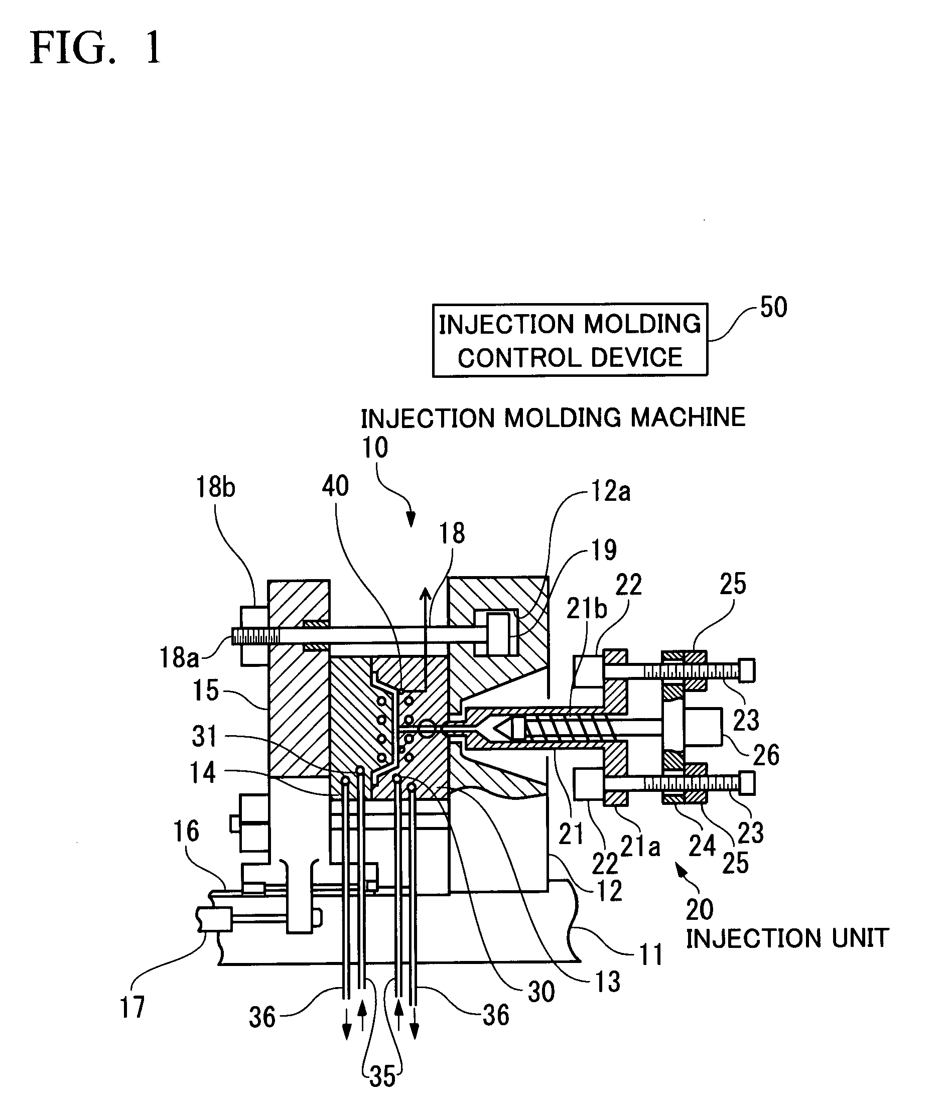
[0063]FIG. 1 is a schematic view of a configuration of an injection molding system (injection molding machine) 10 according to the embodiment.

[0064]As shown in FIG. 1, in a mold clamping device (mold driving unit) of the injection molding system 10, a fixed die plate 12 is secured to a base 11 and a fixed mold 13 is mounted to the fixed die plate 12. A movable mold 14 facing the fixed mold 13 is mounted to a movable die plate 15 placed to face the fixed die plate 12. The movable die plate 15 is guided by a guide rail 16 provided on the base 11, and is movable via a linear bearing while facing the fixed die plate 12. A hydraulic cylinder 17 is used to move the movable die plate 15 for opening and closing a mold.

[0065]A plurality of tie bars 18 are directly connected to rams 19 that slide i...


PUM

PropertyMeasurementUnit
temperatureaaaaaaaaaa
pressureaaaaaaaaaa
glass transition temperatureaaaaaaaaaa

Abstract

There are provided an injection molding system, a computer program, a method of injection molding, and an injection molding machine capable of performing precise temperature control of a mold even when there is a delay in temperature increase of the mold in heat supply with a heating medium. The temperature control is performed so that temperatures of a fixed mold and a movable mold are maintained between an upper limit TU and a lower limit TL of a predetermined temperature range after start of injection of resin during an injection molding cycle. The temperature control of the fixed mold and the movable mold is performed only by switching ON/OFF supply of the heating medium, and cooling with a cooling medium is not performed. In a process of cooling the resin, the temperature control is performed so that the temperatures of the fixed mold and the movable mold are maintained between an upper limit TUa and a lower limit TLa of a temperature range effective for resin annealing by stop of supply of the cooling medium and the supply and stop of the heating medium.

Description

TECHNICAL FIELD [0001]The present invention relates to an injection molding system for injection molding, a method of injection molding, an injection molding machine or the like.BACKGROUND ART [0002]When a temperature of a mold is low in an injection filling step of an injection molding machine, a surface of molten resin filled in a cavity of the mold is rapidly solidified. In this case, a cavity surface of the mold may be insufficiently transferred to a molded product, and a defect referred to as a weld line or a silver streak may occur on a molded product surface.[0003]In order to prevent the defect, a molding method has been proposed in which a heating medium is supplied to a medium passage of a mold during a time between mold opening and completion of resin filling, and a cooling medium is supplied during a time between the completion of resin filling and mold opening in a series of steps including injection filling, pressure retention, cooling, and mold opening and closing. Thu...

Claims


Application Information

Patent Timeline
Patent Type & Authority Applications(United States)
IPC IPC(8): B29C47/92B29C48/92
CPCB29C45/7306B29C47/92B29C45/78B29C45/73
Inventor SHIKASE, YOSHIOHATTORI, MICHITAKANOZAKI, SHIGERUIMAEDA, SATOSHIKARIYA, TOSHIHIKO
Owner MITSUBISHI HEAVY INDS PLASTIC TECH
Why Eureka
Try Eureka