Projector and light source apparatus

a technology of light source apparatus and projector, which is applied in the field of projectors, can solve the problems of projector upsizing, high cooling efficiency cannot be obtained, and the driving noise of the fan is increased in association with the increase in airflow quantity,

Active Publication Date: 2010-02-25
SEIKO EPSON CORP
View PDF1 Cites 20 Cited by
  • Summary
  • Abstract
  • Description
  • Claims
  • Application Information

AI Technical Summary

Benefits of technology

[0049]Preferably, the light source apparatus is used by being stored in the light source absorber provided in the projector for absorbing the heat from the light source apparatus, and the second reflector reflects the light in the infrared region toward the li

Problems solved by technology

In contrast, since the temperature of the optical element is not as high as the light source apparatus, a high cooling efficiency can hardly be obtained even by blowing the air in the same manner as the light source apparatus.
Although the cooling efficiency of the optical element is increased by increasing the airflow quantity of the fan, there arises a problem such that the driving noise of the fan is increased in association with increase in airflow quantity.
However, when the compressor is provided in the projector, there arises a problem such that the projector is upsized due to an installation space of the compressor.
Also, there also arises a problem such that an electric power for operating the compressor is

Method used


Image

  • Projector and light source apparatus
  • Projector and light source apparatus
  • Projector and light source apparatus

Examples


first embodiment

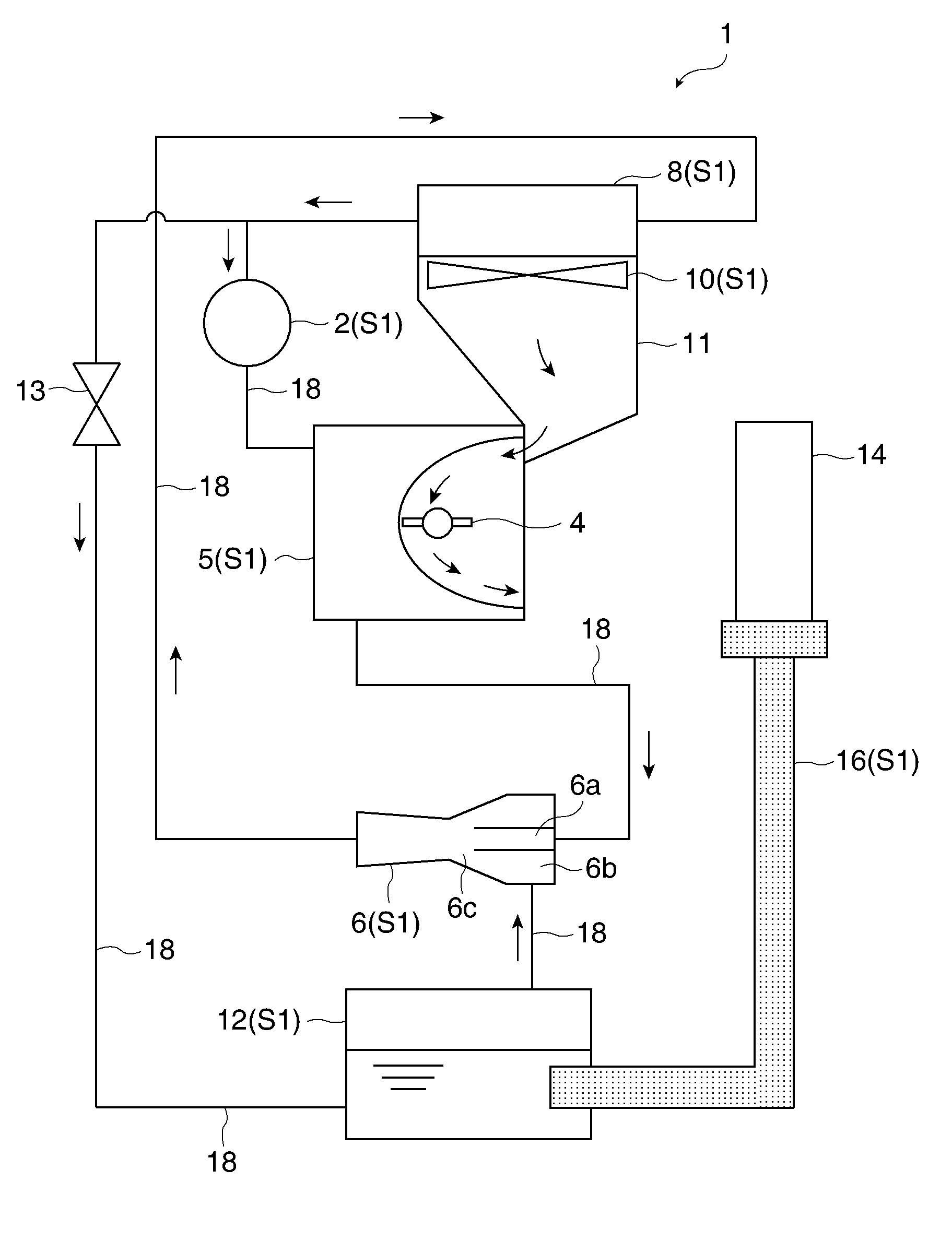
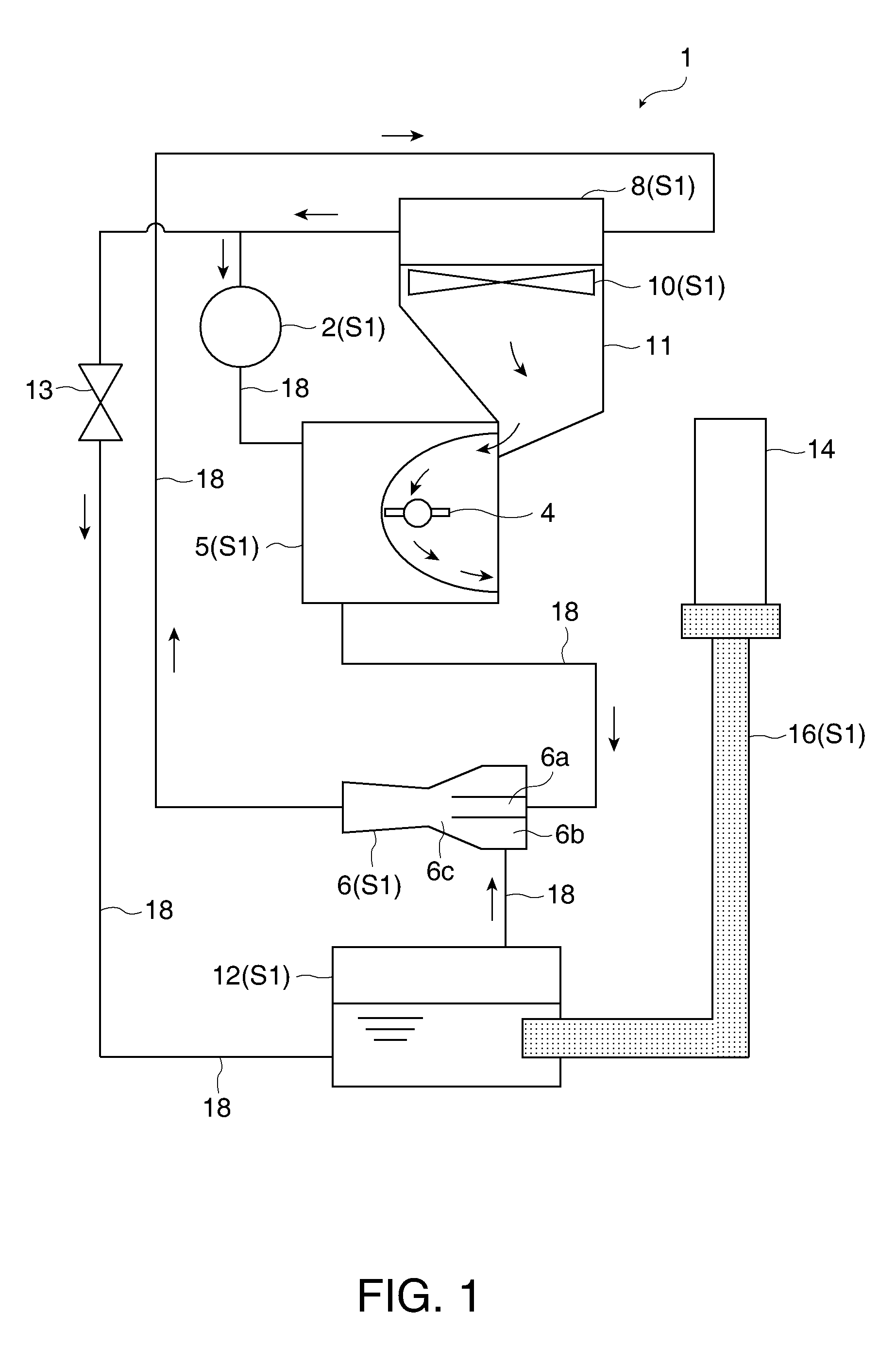
[0068]FIG. 1 shows a schematic configuration of a projector according to a first embodiment. A projector 1 is a front projecting type projector configured to supply light to a screen (not shown) for allowing viewers to appreciate an image by observing light reflected on the screen. The projector 1 cools a light-emitting tube (light source unit) 4 and a spatial light modulator (optical element) 14 as heat sources by a cooling system S1. The cooling system S1 roughly includes a circulating pump 2, an absorbing evaporator 5, an ejector pump 6, a radiator (heat radiator) 8, a cooling fan 10, a low-temperature heat exchanger (evaporator) 12, and a heat transfer unit 16. The circulating pump 2, the absorbing evaporator (light source heat absorber) 5, the ejector pump 6, the radiator 8, and the low-temperature heat exchanger 12 are connected via coolant tubes 18.

[0069]The circulating pump 2 functions as a power source for circulating coolant through the absorbing evaporator 5, the ejector ...

second embodiment

[0090]FIG. 7 shows a schematic configuration of a projector 51 according to a second embodiment. The like elements are designated by the same numbers as in the first embodiment and overlapped description will be omitted. A cooling system S2 of the projector 51 according to the second embodiment is characterized in that the spatial light modulator 14 is cooled using a heat pipe 30 which surrounds the periphery of the spatial light modulator 14 and in that part of the heat pipe 30 is brought into contact with a piping system (heat pipe circulating system) disposed partly in the interior of the evaporator to cause the coolant in the heat pipe circulation system to absorb the heat from the spatial light modulator 14 and cool the same.

[0091]FIG. 8 is a front view of the spatial light modulator 14 and the heat pipe (optical element heat absorber) 30 viewed from the light-emitting tube 4 side. The heat pipe 30 is arranged so as to surround the periphery of the spatial light modulator 14 an...

third embodiment

[0096]FIG. 9 shows a schematic configuration of a projector 101 according to a third embodiment. The like elements are designated by the same numbers as in the first embodiment and overlapped description will be omitted.

[0097]The light-emitting tube 4 is a light source unit configured to emit light including red (R) light, green (G) light, and blue (B) light, and is an extra-high pressure mercury lamp, for example.

[0098]A first integrator lens 112 and a second integrator lens 113 each include a plurality of lens elements arranged in an array. The first integrator lens 112 divides a luminous flux from the light-emitting tube 4 into a plurality of parts. The respective lens elements of the first integrator lens 112 focus the luminous flux from the light-emitting tube 4 in the vicinity of the lens elements of the second integrator lens 113. The lens elements of the second integrator lens 113 form images of the lens elements of the first integrator lens 112 on the spatial light modulato...


PUM


Abstract

A projector includes: a light source unit configured to emit light; a light source heat absorber configured to cause coolant to absorb heat from the light source unit; an ejector pump configured to allow passage of the coolant having absorbed the heat in the light source heat absorber; a radiator configured to radiate the heat of the coolant flowed out from the ejector pump; an evaporator configured to cool the coolant stored in the evaporator by evaporating the coolant; and a heat source other than the light source unit, wherein the ejector pump decompress the interior of the evaporator by a pressure drop due to the passage of the coolant having absorbed the heat in the light source heat absorber, and heat from the heat sources other than the light source unit is absorbed by the coolant cooled by the evaporator.

Description

BACKGROUND[0001]1. Technical Field[0002]The present invention relates to a projector and, more specifically, to a technology of a projector having an ejector pump for cooling a heat source.[0003]2. Related Art[0004]The temperature of a light source apparatus used in a projector rises to a very high temperature such as 800° C. to 1000° C. The projector includes an optical element which modulates light emitted from the light source apparatus. The optical element also generates heat by being irradiated with the light from the light source apparatus and rises in temperature to a level higher than the ambient temperature (for example, to 60° C. to 90° C). Therefore, an air-cooled cooling system which blows air to the light source apparatus or the like with a fan is employed in order to cool the light source apparatus or the optical element.[0005]Since the temperature of the light source apparatus is very high, the temperature difference from an outside air is large. Therefore, a high coo...

Claims


Application Information

Patent Timeline
IPC IPC(8): G03B21/16
CPCG03B21/16
Inventor TAKAGI, KUNIHIKO
Owner SEIKO EPSON CORP
Why Eureka
Try Eureka