Generalized ac-dc synchronous rectification techniques for single- and multi-phase systems

a synchronous rectification and multi-phase technology, applied in the direction of electronic switching, power electronics conversion, pulse technique, etc., can solve the problems of commutation failure, significant contribution to the overall power loss of the power supply, and failure of the successful attempt to provide self-driven full-bridge sr

Active Publication Date: 2010-02-25
CONVENIENTPOWER HK
View PDF23 Cites 40 Cited by
  • Summary
  • Abstract
  • Description
  • Claims
  • Application Information

AI Technical Summary

Problems solved by technology

The conduction loss of a diode rectifier contributes significantly to the overall power loss in a power supply, especially in low out-voltage applications.
From a review of the prior art, however, it can be seen that to date there has been no successful attempt to provide self-driven full-bridge SR.
However, there is a defect in this circuit, As shown in FIG. 3(b), the current loop through M1 and M4 can flow in both directions, because VCSD gate drive cannot detect the reverse current.
Unlike the diodes in FIG. 2, which can automatically turn off when their current reverses, such switches with a bi-directional switch current flow can make the commutation fail.
But the passive capacitor and inductor are large in size and this inevitably creates a large dead-time between the driving pulses that adversely affects the duration of power transfer in one cycle.
This kind of approach has a major limitation.

Method used


Image

  • Generalized ac-dc synchronous rectification techniques for single- and multi-phase systems
  • Generalized ac-dc synchronous rectification techniques for single- and multi-phase systems
  • Generalized ac-dc synchronous rectification techniques for single- and multi-phase systems

Examples


example 1

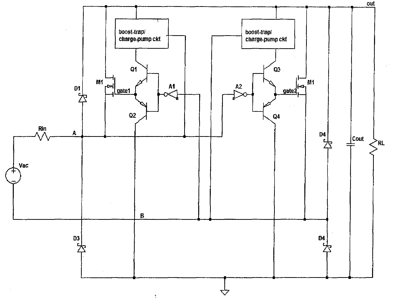
[0090]A first embodiment of the invention may take the form of a current-source input upper half VCSD full-bridge synchronous rectification (SR) as shown in FIG. 11.

[0091]Two p-type power MOSFETs, M1 and M2, replace the upper diodes (D1 and D2 in FIG. 2) of the left and right branches of the diode-bridge. Dm1 and Dm2 can be either the body diode of the two MOSFETs or added external diodes. In this configuration MOSFET M1 has its gate signal controlled by VB and MOSFET M2 has its gate signal controlled by voltage VA. Both MOSFET gates are cross-connected against the current-source input terminals (point A and point B) through the complementary gate drive circuits formed by the Q1-Q2 pair and Q3-Q4 pair. A gate drive buffer (totem poles, drivers or direct connection) between the current-source input and the MOSFETs can be used to drive the power switches to be ON / OFF accordingly.

[0092]In FIG. 12 and FIG. 13, at time t0 the current direction of the current source starts from point A to...

example 2

[0096]In order to further reduce the power loss in the diodes, a second embodiment of the invention comprises current-source input upper half VCSD and lower half current controlled self-driven' (CCSD) full-bridge synchronous rectification (SR) as shown in FIG. 15. In this case D3 and D4 in FIG. 5 are replaced with two n-type MOSFETs, M3 and M4, respectively.

[0097]As shown in FIG. 15, sensing resistors Rsen1 and Rsen2 are placed at both sides of the lower legs for detecting the current flow direction of M3 and M4 (defining positive current flow from ground up to Vout). Comparators U1 and U2 are used to produce driving pulses according to the current flow direction at Rsen1 and Rsen2. The voltage supplies of U1 and U2 can be directly derived from the rectified DC bulk voltage at the DC output, Vout, as this is the most cost effective method (or indirectly derived from an auxiliary power supply). A positive current through M3 and Dm3 or M4 and Dm4 will cause the output of comparator U1...

example 3

[0102]A third embodiment of the invention may take the form of voltage-source input upper half VCSD lower half CCSD full-bridge synchronous rectification as shown in FIG. 19.

[0103]The input of the proposed full-bridge SR can also be a voltage source, besides the current source in examples 1 and 2. A full version of voltage-source-input self-driven full-bridge SR is shown in FIG. 19. Sensing resistors Rsen1 and Rsen2 are placed at both the lower legs of the bridge for detecting the current flow direction (defining positive current flow from ground up to Vout). Comparator U1 and U2 are used to produce driving pulses according to the current flow direction at Rsen1 and Rsen2. A positive current at M3 and Dm3 or M4 and Dm4 will make output of comparator U1 or U2 go to high level. The high voltage level of the comparator, in turn, will drive the buffer Q5 or Q7 (totem pole or driver). Power switch M3 or M4 will be turned ON according to its positive current flow direction and it will be ...


PUM


Abstract

Various circuit configurations and topologies are provided for single and multi-phase, single-level or multi-level, full and half-bridge rectifiers in which diodes are replaced by combinations of voltage-controlled self-driven active switches, current-controlled self-driven active switches and inductors in order to reduce the effects of conduction loss in the diodes.

Description

CROSS-REFERENCE TO RELATED APPLICATION[0001]This application is a Continuation-In-Part (CIP) application of co-pending U.S. patent application Ser. No. 12 / 194,921, filed Aug. 20, 2008, entitled “Single-Phase Self-Driven Full Bridge Synchronous Rectification”, which is hereby incorporated herein by reference in its entirety.FIELD OF THE INVENTION[0002]The present invention relates to methods and circuits for self-driven half- and full-bridge synchronous rectification, and in particular to generalized synchronous rectification techniques for single-phase to multi-phase, and to multi-level AC-to-DC power conversion.BACKGROUND OF THE INVENTION[0003]The conduction loss of a diode rectifier contributes significantly to the overall power loss in a power supply, especially in low out-voltage applications. The rectifier conduction loss is the product of its forward-voltage drop, VF, and the forward conduction current IF. FIG. 1(a) shows one kind of rectifier circuit known as a ‘current doubl...

Claims


Application Information

Patent Timeline
Patent Type & Authority Applications(United States)
IPC IPC(8): H02M7/217
CPCH02M7/219H02M2007/2195Y02B70/1408H03K2017/307H03K17/302H03K17/74H03K17/06H02M1/08Y02B70/10H02M7/2195H02M1/0085
Inventor HO, WING CHOIHUI, RON SHU YUENLIU, XUNCHOI, WAI PONG
Owner CONVENIENTPOWER HK
Why Eureka
Try Eureka