Carbon-dioxide-capture-type steam power generation system

a technology of carbon dioxide and power generation system, which is applied in the direction of lighting and heating apparatus, separation process, emission prevention, etc., can solve the problems difficulty in achieving the saturation temperature of turbine steam, and lowering power generation efficiency in the carbon dioxide-capture-type steam power generation system. achieve the effect of lowering power generation efficiency and high efficiency

Inactive Publication Date: 2010-03-04
KK TOSHIBA
View PDF10 Cites 62 Cited by
  • Summary
  • Abstract
  • Description
  • Claims
  • Application Information

AI Technical Summary

Benefits of technology

[0017]The present invention was made in light of the above problems. That is to say, it is an object of this invention to provide a new carbon-dioxide-capture-type steam power generation system that can successfully restrain the power generation efficiency from lowering.
[0019]According to this invention, the heating-medium heated by the exhaust gas passing through the flue of the boiler, is supplied to the boiler. The absorbing solution is heated in the reboiler by this heating-medium as heat source so as to produce regenerating steam, and then the produced regenerating steam is supplied to the regenerating unit. Namely, by utilizing heat of the exhaust gas discharged from the boiler as energy required for heating the absorbing solution in the reboiler, the carbon dioxide can be released, with high efficiency, from the absorbing solution absorbing the carbon dioxide in the regenerating unit. Therefore, lowering of power generation efficiency in the carbon-dioxide-capture-type steam power generation system can be successfully restrained.

Problems solved by technology

This leads to lowering of the power generation efficiency.
However, in the case of capturing the carbon dioxide without utilizing the aqueous amine compound solution, it has been also reported that the power generation efficiency may be further lowered.
Thus, even if the degree of vacuum is substantially elevated in a steam outlet of the low pressure steam turbine, it becomes quite difficult that the turbine steam can reach a saturated temperature at the steam outlet of the low pressure steam turbine.
In such a case, it also is difficult to keep the turbine steam in an adequately wet state.
Therefore, a dried state and a wet state are alternately repeated (or a dry-wet cyclic state is generated), in a final stage blade of the low pressure steam turbine, leading to serious corrosion of the final stage blade.
Therefore, in the case of considerably elevating the temperature of the turbine steam, the degree of superheating the extraction steam tend to be excessively increased, causing the feed-water heater to be unduly deformed.

Method used


Image

  • Carbon-dioxide-capture-type steam power generation system
  • Carbon-dioxide-capture-type steam power generation system
  • Carbon-dioxide-capture-type steam power generation system

Examples


first embodiment

[0023]Hereinafter, one exemplary embodiment of the present invention will be described with reference to the drawings.

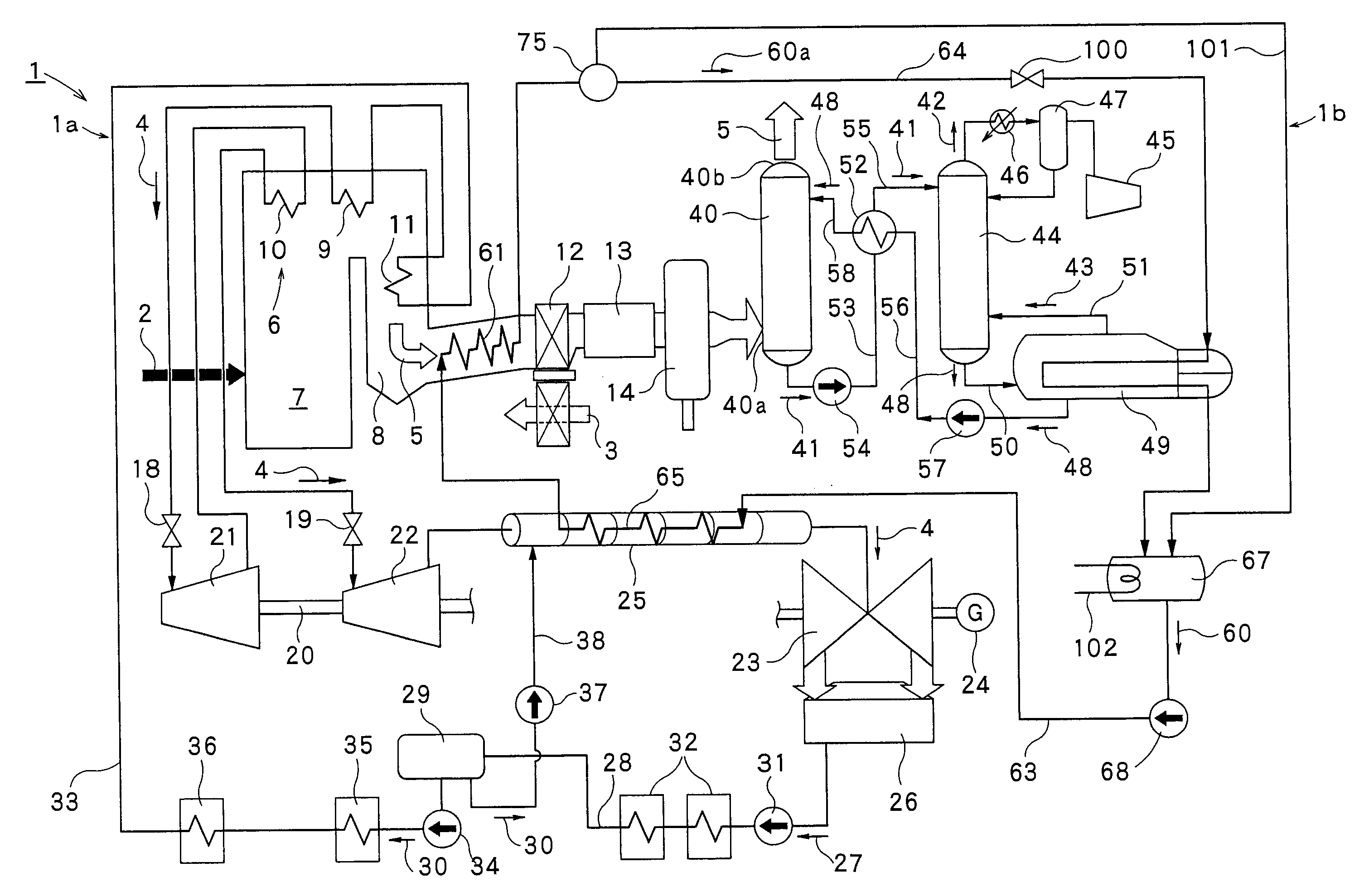
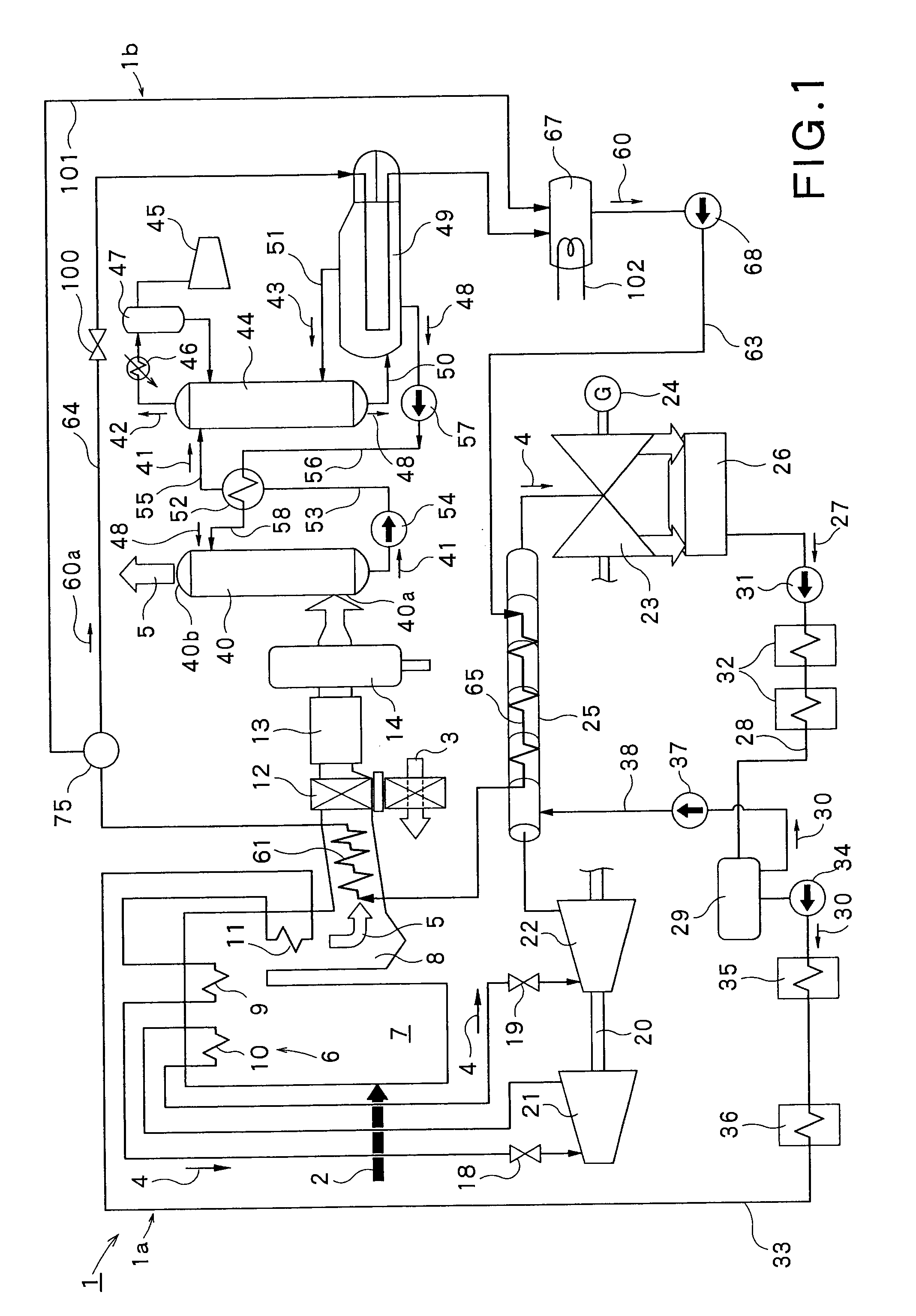
[0024]First, the carbon-dioxide-capture-type steam power generation system 1 according to this invention will be described. As shown in FIG. 1, the carbon-dioxide-capture-type steam power generation system 1 includes a steam power generation plant 1a for producing turbine a steam 4 by combusting a fuel 2, so as to generate electric power by rotating a turbine, and a carbon dioxide capturing plant 1b for capturing the carbon dioxide by using an absorbing solution for absorbing the carbon dioxide contained in an exhaust gas 5 which is produced in a boiler 6.

[0025]The steam power generation plant 1a, as shown in FIG. 1, comprises the boiler 6 being configured to receive the fuel 2 and a combustion air 3 and produce the turbine steam 4 and the exhaust gas 5 by combusting the fuel 2 and the combustion air 3. This boiler 6 has a furnace 7 configured to combust the fuel 2 a...

second embodiment

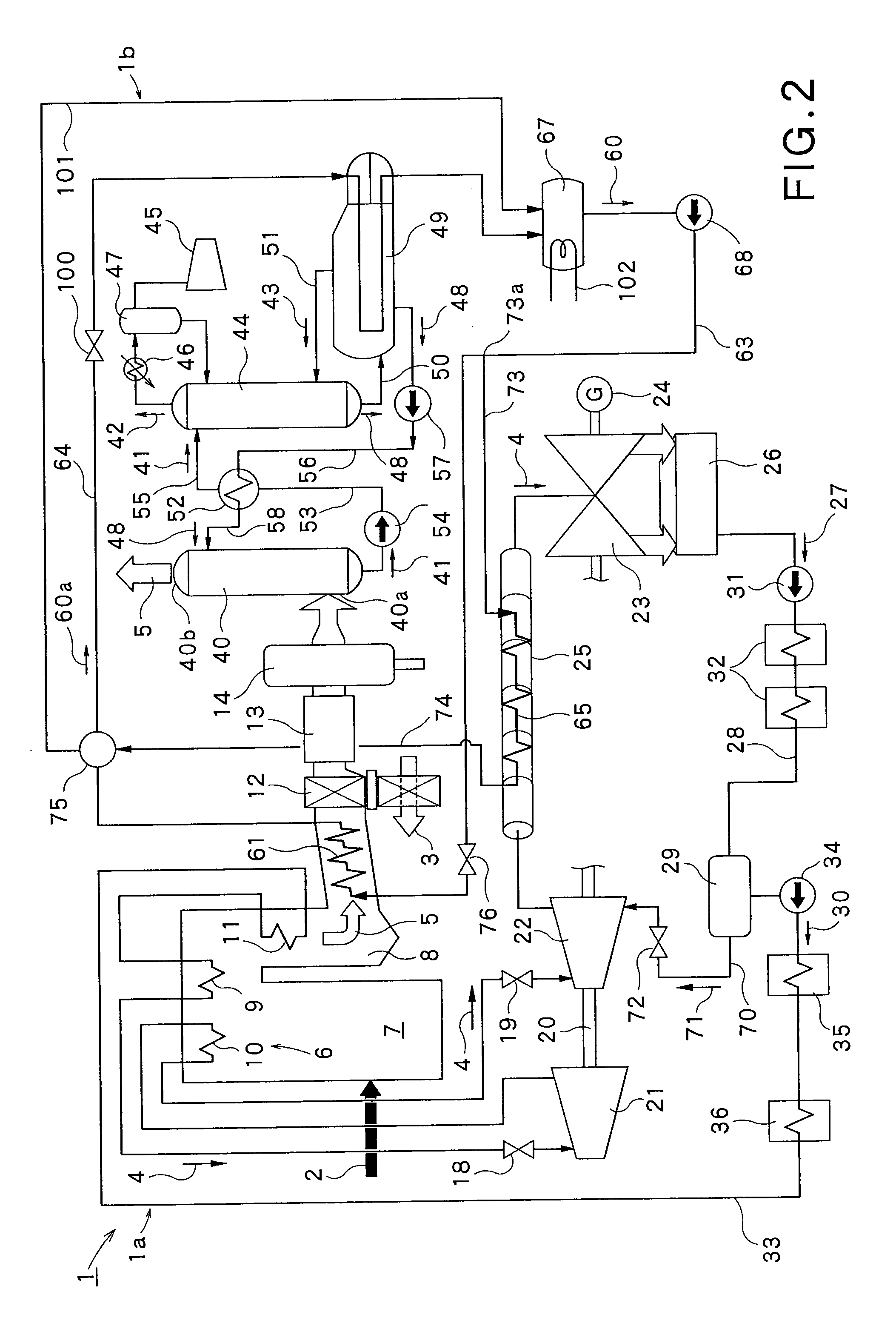
[0080]Next, referring to FIG. 2, the carbon-dioxide-capture-type steam power generation system according to a second embodiment of the present invention will be described.

[0081]The second embodiment shown in FIG. 2 is different from the first embodiment shown in FIG. 1, mainly in that the turbine-side heat exchanger is arranged in parallel with the boiler-side heat exchanger, and the deaerated steam produced by deaerating the condensed water in the deaerator is supplied to the outlet of the intermediate pressure turbine. In regard to the other construction, however, the second embodiment is substantially the same as the first embodiment. It is noted that like parts depicted in FIG. 2 are respectively designated by like reference numerals respectively assigned to those depicted in FIG. 1, and such parts will not be further described below.

[0082]In the carbon-dioxide-capture-type steam power generation system 1 shown in FIG. 2, a deaerated steam supply line 70 is connected to the deae...

third embodiment

[0090]Now, referring to FIG. 3, the carbon-dioxide-capture-type steam power generation system according to a third embodiment of the present invention will be described.

[0091]The third embodiment shown in FIG. 3 is different from the first embodiment shown in FIG. 1, mainly in that a deaerated water-steam heater heating the deaerated water-steam taken out from the deaerator is provided in the deaerated water-steam supply line, and a steam-water separation header for the deaerated water-steam, separating the water from the deaerated water-steam, is provided on the downstream side of the deaerated water-steam heater. In regard to the other construction, however, the third embodiment is substantially the same as the first embodiment. It is noted that like parts depicted in FIG. 3 are respectively designated by like reference numerals respectively assigned to those depicted in FIG. 1, and such parts will not be further described below.

[0092]In the carbon-dioxide-capture-type steam power...


PUM

PropertyMeasurementUnit
temperatureaaaaaaaaaa
pressureaaaaaaaaaa

Abstract

A carbon-dioxide-capture-type steam power generation system 1 according to the present invention comprises a boiler 6 producing an exhaust gas 5 by combusting a fuel 2 and having a flue 8; an absorbing unit 40 being configured to absorb the carbon-dioxide contained in the exhaust gas 5 into an absorbing solution; and a regenerating unit 44 being configured to release the carbon dioxide gas from the absorbing solution absorbing the carbon dioxide and discharge the released carbon dioxide gas. Further, in this system, a reboiler 49 is provided for receiving a heating-medium as heat source, producing a steam 43 and supplying the produced steam 43 to the regenerating unit 44. Additionally, in the flue 8 of the boiler 6, a boiler-side heat exchanger 61 is provided for heating the heating-medium by the exhaust gas 5 passing therethrough.

Description

BACKGROUND[0001]1. Technology Field[0002]The present invention relates to a carbon-dioxide-capture-type steam power generation system for capturing carbon dioxide from exhaust gas produced when steam is produced by combusting fuel in a boiler, by using an absorbing solution for absorbing the carbon dioxide, while generating electric power. In particular, this invention relates to the carbon-dioxide-capture-type steam power generation system which can restrain the power generation efficiency from lowering and can take out energy required for capturing the carbon dioxide from the exhaust gas.[0003]2. Background Art[0004]Recently, in the field of thermal power generation equipment, intensive study for enhancing power generation efficiency has been made in view of environmental preservation. For instance, in usual thermal power generation equipment, the temperature of the steam used for operation of a steam turbine is 600° C. or so. However, the recent study has been aimed at enhancing ...

Claims


Application Information

Patent Timeline
Patent Type & Authority Applications(United States)
IPC IPC(8): F01K13/00F23J15/02F01K7/16F01K11/02C01B32/50
CPCF01K7/22F01K17/06F23J15/006Y02C10/06F23J2219/40Y02C10/04F23J2215/50B01D53/1475B01D2257/504B01D2258/0283B01D2259/65Y02C20/40Y02E20/32Y02P20/129B01D53/18B01D53/62F01K11/02F01K13/00F01K17/00F23J15/08
Inventor YAMASHITA, KATSUYAINOMATA, ASAKOOOHASHI, YUKIOOGAWA, TAKASHIIKEDA, KAZUTAKASUGA, TAKEO
Owner KK TOSHIBA
Why Eureka
Try Eureka