
System and method for space elevator deployment

a technology for space elevators and systems, applied in the field of systems and methods for space elevator deployment, can solve problems such as problematic initial deployment of space elevators, achieve the effects of facilitating capture, fuel-wise inefficient, and high density and/or radar reflectivity

Inactive Publication Date: 2010-03-04
DEMPSEY JAMES G
View PDF7 Cites 9 Cited by
  • Summary
  • Abstract
  • Description
  • Claims
  • Application Information

AI Technical Summary

Benefits of technology

[0010]A beacon satellite is discharged from the deployment vehicle into an orbital path which will precede the orbital path of the inertial mass object. The purpose of the beacon satellite is to provide an orbital reference point for use in station keeping of the inertial mass object. During deployment the beacon satellite will experience the same tidal effects as does the inertial mass object but without the unbalanced tensions imparted on the inertial mass object by the deploying tethers.

Problems solved by technology

Although the finished structure is relatively well understood by those familiar with the art, the initial deployment of the space elevator is problematic.

Method used


Image

  • System and method for space elevator deployment
  • System and method for space elevator deployment
  • System and method for space elevator deployment

Examples


Embodiment Construction

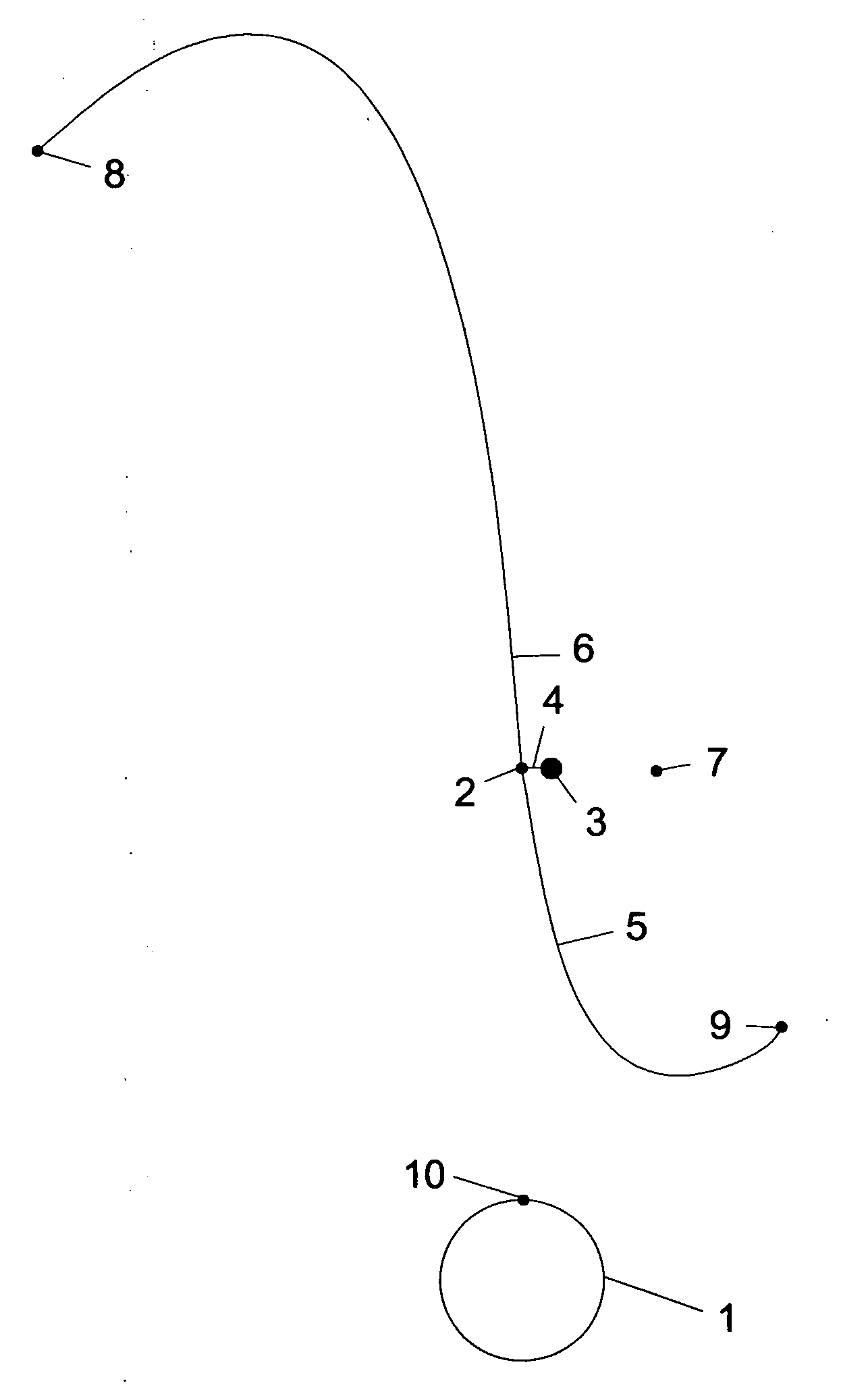
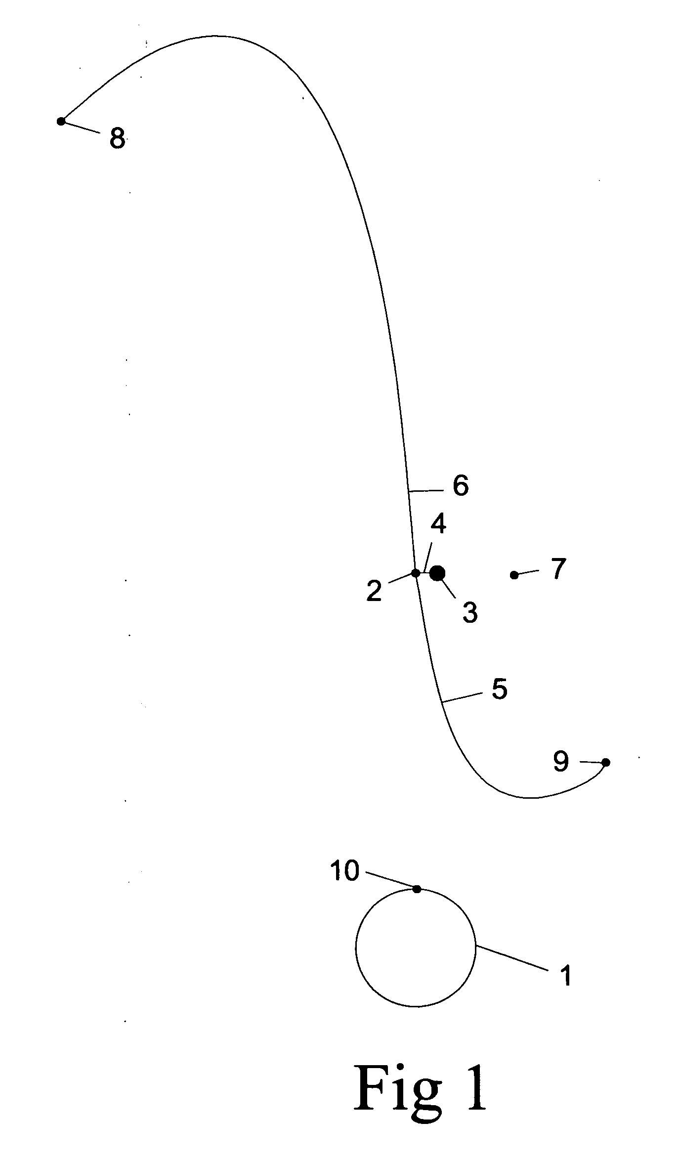
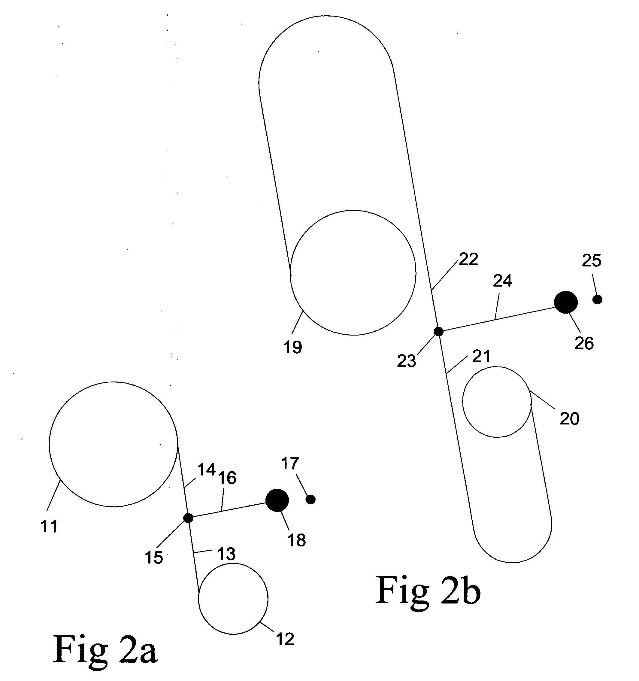
[0033]Tether material of sufficient properties and dimensions and of length of approximately 100,000 kilometers is wound onto two spools, shown as 11 and 12 in FIG. 2a and 19, 20 in FIG. 2b, and for secondary tether deployment as 41 and 42 in FIG. 4a. Approximately ⅔rd of the material representing the outbound portion of the tether is wound on an upper spool show as 11 in FIG. 2a and 19 in FIG. 2b and for secondary tether deployment shown as 41 in FIG. 4a, and the upper portion of tether, shown as 6 in FIG. 1, 14 in FIG. 2a, 22 in FIG. 2b, 30 in FIG. 3a, 34 in FIG. 3b, 39 in FIG. 4a, 48 in FIG. 4b, and 68 in FIG. 6b. The remainder of the tether, less a portion of tether between the spools, shown as 13, 14 in FIG. 2a, is wound onto a second spool, shown as 12 in FIG. 2a, and 20 in FIG. 2b, and for secondary tether deployment, shown as 42 in FIG. 4a, and the lower portion of the tether, shown as 5 in FIG. 1, 13 in FIG. 2a, 21 in FIG. 2b, 28 in FIG. 3a, 32 in FIG. 3b, 37 in FIG. 4a, 46...


PUM


Abstract

A system and method for the initial deployment of a space elevator using a tether, doubly spooled from each end, an inertial mass, beacon satellite and positional thrusters, whereby tether is de-spooled from geosynchronous Earth orbit altitude, using gravity and centripetal force gradient, and timed such that when the tethers fully de-spool or near the point of being fully de-spooled, are released and the free ends, one left to fall inwards to Earth anchor point, and the other left to fall outwards to tether end ballast support point, result in an Earth anchored self supporting tension structure.

Description

CROSS-REFERENCE TO RELATED APPLICATIONS[0001]U.S. Pat. No. 6,981,674 Jan. 3, 2006 DempseySTATEMENT REGARDING FEDERALLY SPONSORED RESEARCH OR DEVELOPMENT[0002]Not ApplicableREFERENCE TO A SEQUENCE LISTING, A TABLE, OR A COMPUTER PROGRAM, LISTING COMPACT DISC APPENDIX[0003]NoneBACKGROUND OF THE INVENTION[0004]A space elevator is a self supporting tension structure consisting primarily of a tether attached at one end near the Earth equator and the other end extending radially outwards. When the tether has sufficient length, approximately 100,000 kilometers, the aggregate centripetal force along the full length of tether exceeds the aggregate gravitational force permitting the tether to become self supporting. Once the space elevator is installed, climbing devices will clamp on to the tether and will be electrically driven up or down the tether to deliver a payload to a desired altitude.[0005]Although the finished structure is relatively well understood by those familiar with the art, t...

Claims


Application Information

Patent Timeline
IPC IPC(8): B64G1/10B64G1/22B64G1/66B64G1/24
CPCB64D17/80B64G1/002B64G1/648B64G1/007B64G1/2427
Inventor DEMPSEY, JAMES G.
Owner DEMPSEY JAMES G
Learn More