Bio-energy system and apparatus

a bio-energy system and apparatus technology, applied in the field of bio-energy systems and apparatuses, can solve the problems of detachment of baffles from the drum wall, cracking of the drum side wall, and relative corrosion of the environment within the drum, and achieve the effect of enhancing the impact absorption

Inactive Publication Date: 2010-03-04
BEDMINSTER INT
View PDF7 Cites 3 Cited by
  • Summary
  • Abstract
  • Description
  • Claims
  • Application Information

AI Technical Summary

Benefits of technology

[0038]In a particularly preferred embodiment the cylindrical drum is protected internally by longitudinal stress bars fixed to an inside face of the drum and extending along the length of the drum, each of said stress bars projecting inwardly from the inside face of the drum. Ideally the stress bars are approximately four to five inches (100 mm-12

Problems solved by technology

During processing of the material in the drum a relatively corrosive environment is generated within the drum.
In such a corrosive environment the welds can fail, leading to detachment of the baffles from the wall of the drum.
In extreme cases the drum side-wall will crack.
This is undesirable from an environmental point of view.
However

Method used


Image

  • Bio-energy system and apparatus
  • Bio-energy system and apparatus
  • Bio-energy system and apparatus

Examples


Embodiment Construction

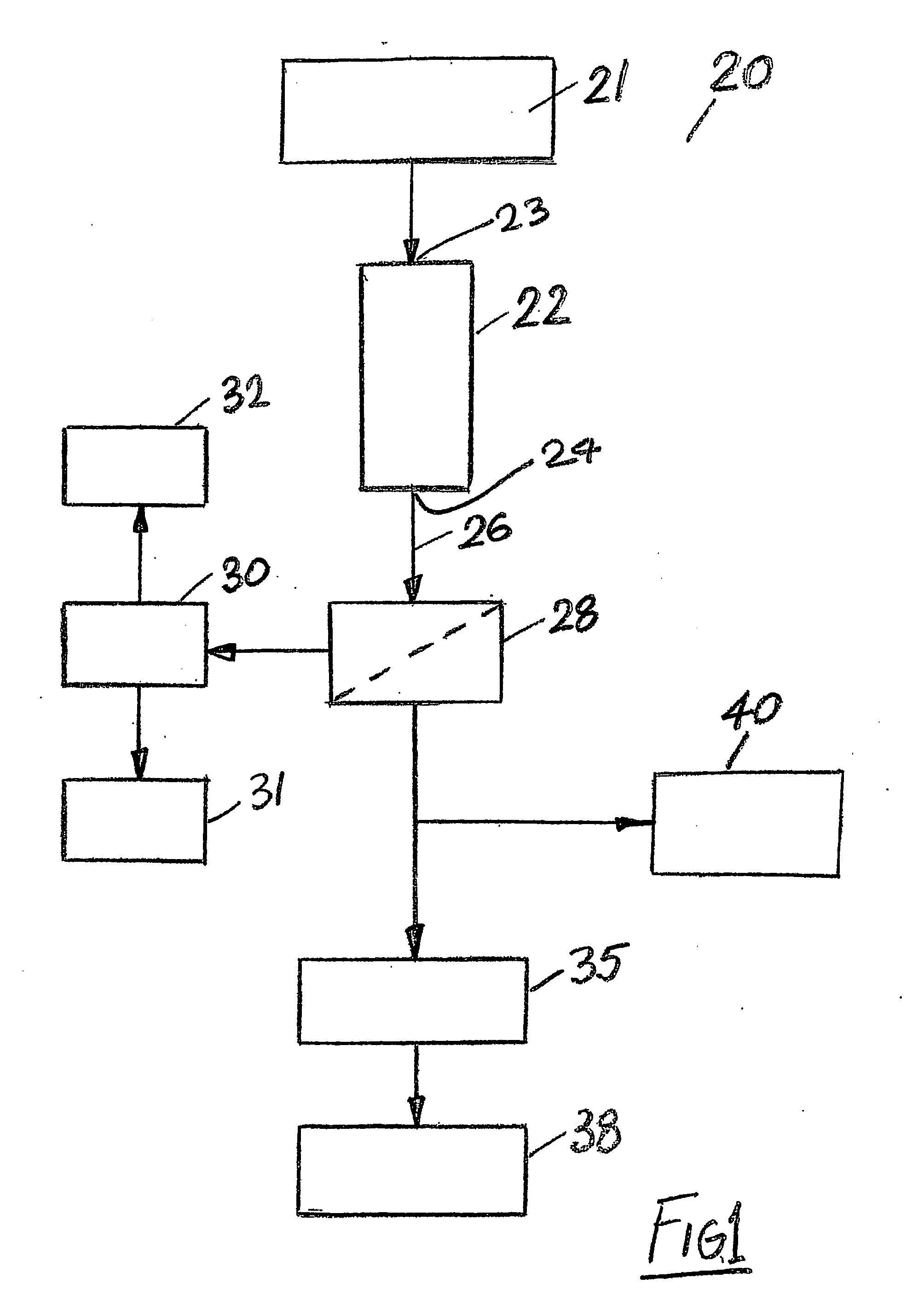
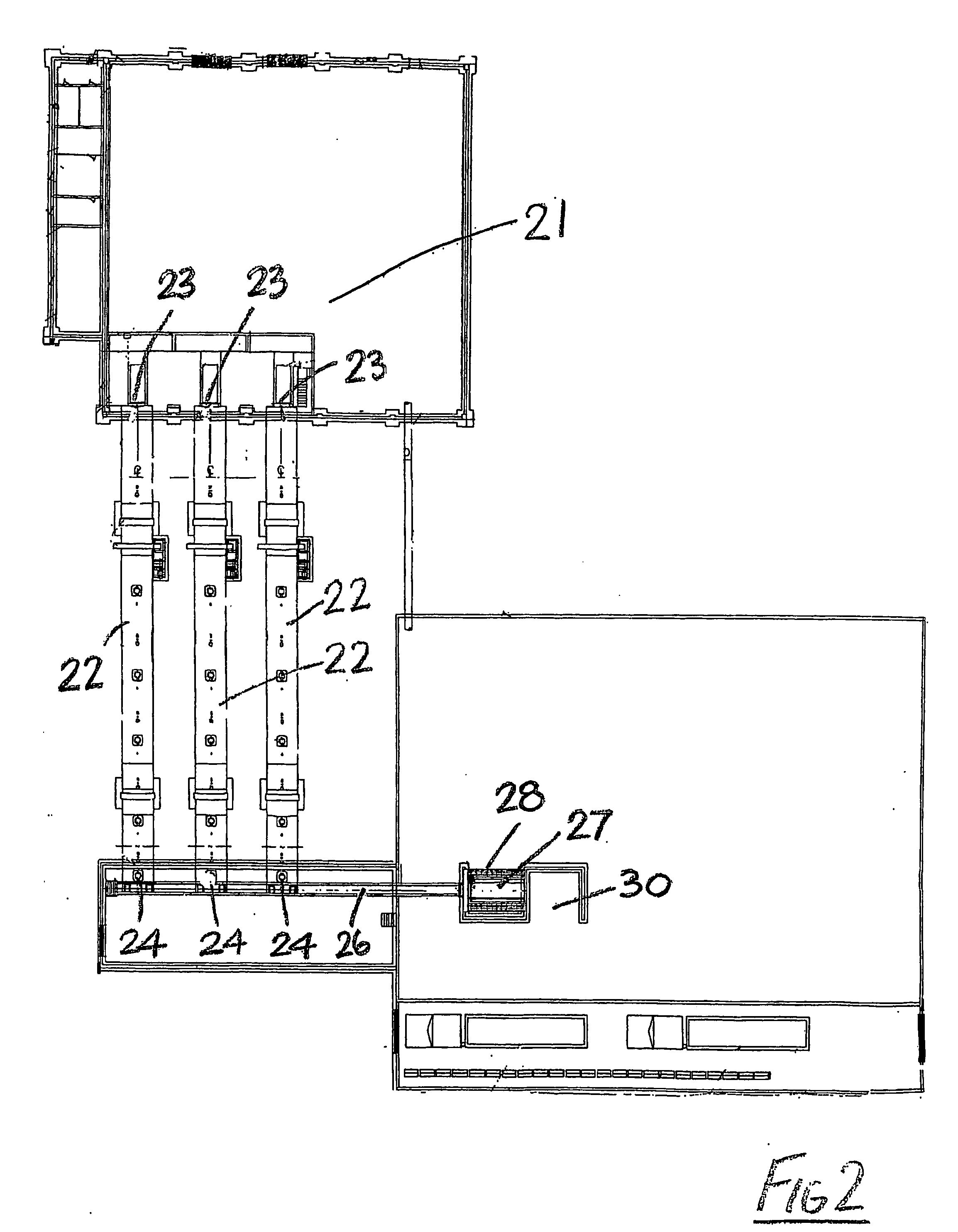
[0052]Referring to the drawings, and initially to FIGS. 1 and 2 thereof, there is illustrated a bio-energy system according to the invention indicated generally by the reference numeral 20. The system 20 includes a waste collecting station 21 at which raw waste material such as municipal waste, household waste and the like is collected. This raw waste material is then fed to an inlet of a rotary organic material digester 22. The raw waste material is delivered through the rotary digester 22 in a controlled manner between an inlet 23 and an outlet 24 of the digester 22 for converting the organic waste material content of the raw waste material to a bio-fuel.

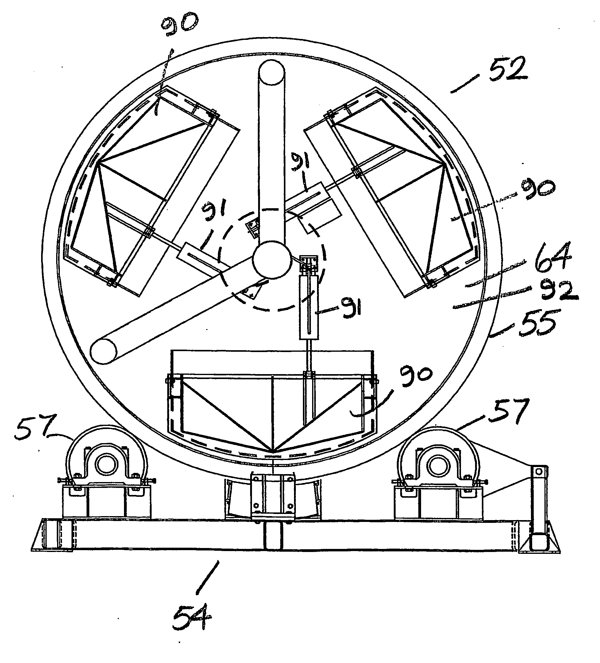
[0053]The rotary organic material digester 22 includes a cylindrical drum having a raw material inlet 23 at one end and a treated material outlet 24 at the other end. The cylindrical drum is rotatably mounted on a support for rotation about a central axis of the drum. The rotational axis of the drum is inclined downwardly between ...


PUM


Abstract

A bio-energy system includes a waste collecting station at which raw waste material such as municipal waste, household waste and the like is collected. The waste is delivered through a rotating organic material digester in a controlled manner for converting the organic waste material content of the raw waste to a bio-fuel. Treated material discharged from the digester is passed through a screen to remove any inorganic materials, leaving the bio-fuel. The bio-fuel is dried at a drying station and then delivered to a boiler for combustion to generate energy.

Description

BACKGROUND OF THE INVENTION[0001]This invention relates to bio-energy systems and apparatus.[0002]In U.S. Pat. No. 5,047,349 and U.S. Pat. No. 5,407,809 for example there are described systems and apparatus for converting organic waste material such as municipal waste into compost. The system shown in U.S. Pat. No. 5,047,349 operates in a batch treatment system, whilst the system of U.S. Pat. No. 5,407,809 is a continuous feed process. The content of these documents is included herein by reference. Each of these systems include a digester of the type comprising a cylindrical drum having an organic material inlet at one end and a treated material outlet at its other end, said cylindrical drum being rotatably mounted on a support for rotation about a central axis of the drum, means for rotating the drum on the support, the rotational axis of the drum being inclined downwardly between the inlet and the outlet of the drum to feed material between the inlet and the outlet, a plurality of...

Claims


Application Information

Patent Timeline
IPC IPC(8): A62D3/02A62B29/00
CPCC05F17/00C10L5/44Y02E50/30Y02E50/10C10L5/46Y02P20/133Y02P20/145Y02W30/40
Inventor O'KANE, PEARSE
Owner BEDMINSTER INT
Why Eureka
Try Eureka