Process of fabricating a workpiece using a test mask

a technology of workpieces and masks, applied in the direction of measurement devices, semiconductor/solid-state device testing/measurement, instruments, etc., can solve the problems of no flexibility in changing the sample size (i.e., number of dedicated test structures) without changing the product, and the test workpiece may not yield accurate information regarding the integration of the process

Inactive Publication Date: 2010-03-04
CYPRESS SEMICON CORP
View PDF7 Cites 91 Cited by
  • Summary
  • Abstract
  • Description
  • Claims
  • Application Information

AI Technical Summary

Problems solved by technology

However, the omitted processing operation may have an actual significant impact on the process integration, and therefore, the test workpieces may not yield accurate information regarding a process integration issue.
With either option, there is no flexibility in changing the sample size (i.e., number of dedicated test structures) without changing the product masks, which can be expensive and risky, particularly for product masks having small feature sizes and requiring precise alignment.
Dedicated test structures in the scribe lines may provide insufficient or inaccurate information.
The amount of data collected for any particular type of test structure may be limited by the size of the scribe lines and the number of other types of dedicated test structures, alignment marks, etc.
Therefore, the amount of data may be too small to correctly isolate a cause of a problem.
Also, the dedicated test structures in the scribe lines may not accurately reflect processing conditions near the center of an immediately adjacent product die.
For example, a problem with etching densely populated features within the product die may not be detected by a dedicated test structure in the scribe lines because there may be insufficient area within the scribe lane to replicate the feature density near the c...

Method used


Image

  • Process of fabricating a workpiece using a test mask
  • Process of fabricating a workpiece using a test mask
  • Process of fabricating a workpiece using a test mask

Examples


example 1

[0051]Example 1 demonstrates how the concepts as described above can be used with respect to forming and testing conductive lines, such as word lines within a memory sector, without any need of bond or test pads on the product die. While many details are provided with respect to materials, thicknesses, and formation techniques, such details are merely illustrative and not meant to limit the scope of the present invention.

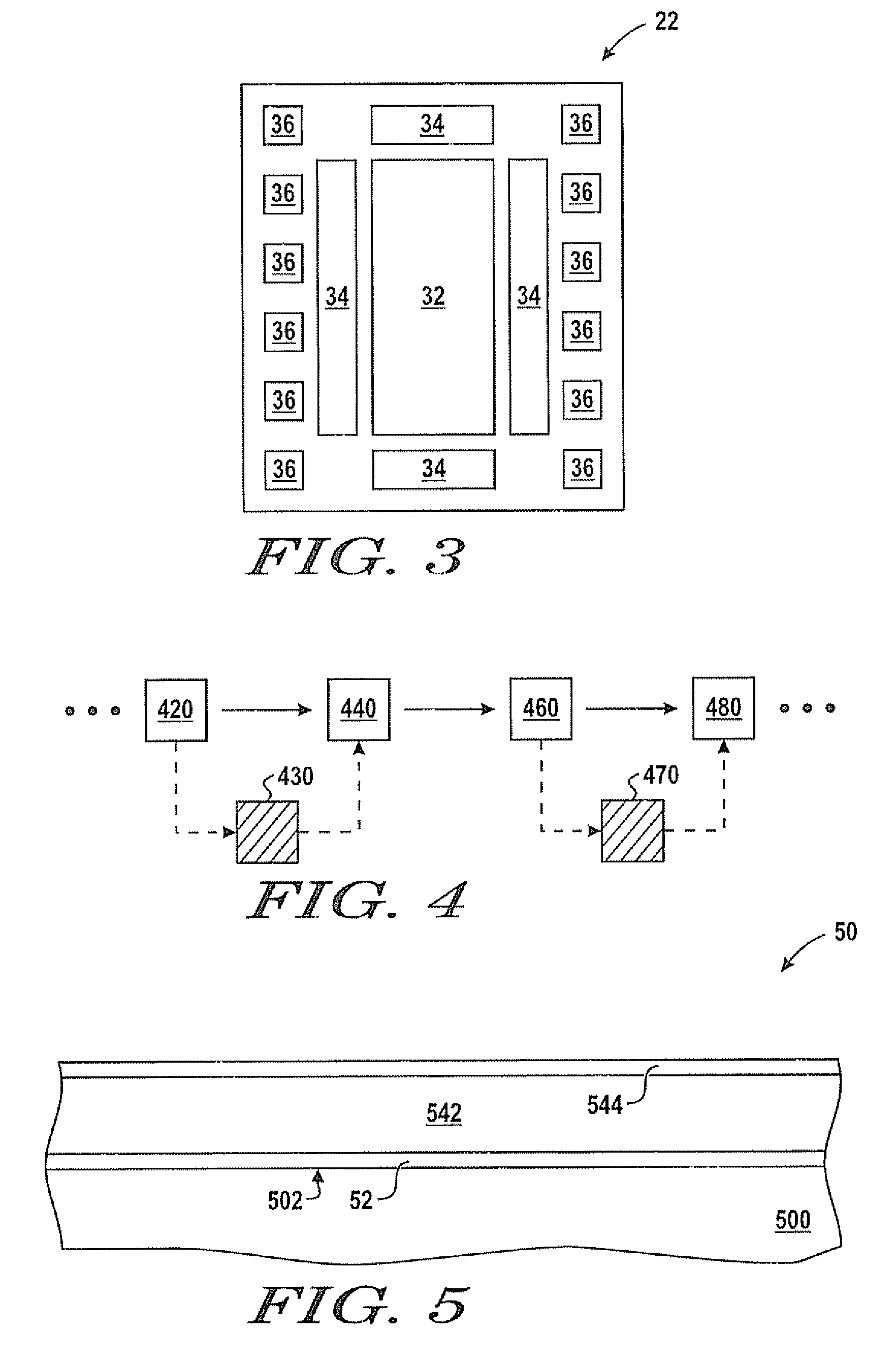
[0052]Attention is now directed to a process of fabricating a product workpiece. FIG. 5 includes an illustration of a cross-sectional view of a portion of a product workpiece 50 that includes a substrate 500 and layers formed thereon. The portion of the product workpiece 50, as illustrated in FIG. 5, includes part of a partially fabricated product die. The substrate 500 can include a monocrystalline semiconductor wafer, a semiconductor-on-insulator wafer, a flat panel display (e.g., a silicon layer over a glass plate), or other substrate used to form electronic devi...

example 2

[0076]Example 2 demonstrates how the concepts as described herein can be extended to other stacks that define openings having aspect ratios that are even larger than the embodiments as described with respect to Example 1.

[0077]FIG. 14 includes an illustration of a portion of a workpiece that includes a substrate 1400, a dielectric layer 1422, a patterned conductive layer 1442, another patterned conductive layer 1444, and a mask layer 1462. Such a structure may be formed as part of an integrated circuit having different work functions for n-channel and p-channel transistors. For example, the patterned conductive layer 1442 may be designed to achieve a particular work function, and the other patterned conductive layer 1444 may be a conductive strapping layer, such as doped polysilicon. With more layers, the openings between the features as illustrated in FIG. 14 are deeper, and thus, the aspect ratio of the openings is larger. Defects 1482 and 1484 lie along the bottoms of the opening...

example 3

[0080]Example 3 demonstrates how the concepts as described herein can be extended to surface topologies that may hide a defect, such it may not be seen from a top view of a workpiece.

[0081]FIGS. 16 to 19 include illustrations at a point in processing similar to the embodiment as described with respect to FIG. 9. Unlike the embodiment illustrated in FIG. 9, a feature has an overhanging portion that can make detection of a defect by optical methods nearly impossible.

[0082]Referring to FIGS. 16 and 17, a dielectric layer 1622 and a patterned insulating layer 1624 overlie a substrate 1600. Word lines 1642 and 1644 are similar to word lines 92 and 94. Word lines 1644 have been severed to define gaps 1646 between flared portions 1648 and 1649. Each of the word lines 1642 and 1644 include a conductive layer 1662 and a hard mask layer 1664. The dielectric layer 1622, the conductive layer 1662 and the hard mask layer 1664 can have any of the films, materials, thicknesses, and formation techn...


PUM


Abstract

A product workpiece can be processed to form product dice. A test mask can allow intentional changes to be made to a feature on the product workpiece to examine how the altered feature performs. Use of the test mask may be used or not used based on the needs or desires of skilled artisans. By using the test mask, a separate dedicated test structure is not required to be formed in a scribe lane or within an area that could otherwise be used for a product die. Thus, the sampling level by using the test mask can be varied. Also, separate test workpieces, which may not be processed using a significantly different process flow or at significantly different times as compared to product workpieces, are not required. The product workpiece with the altered feature can be electrically tested without the need to form test or bond pads.

Description

BACKGROUND[0001]1. Field of the Disclosure[0002]This disclosure relates to processes of fabricating workpieces, and more particularly to, processes of fabricating workpieces using test masks.[0003]2. Description of the Related Art[0004]Dedicated test structures are extensively used on test workpieces (not sold for revenue) or on product workpieces (include product dice that can be sold for revenue) to gain information regarding the shape or performance of electrical components or other features. Test workpieces typically have process flows and masks that are different from process flows and masks used for product workpieces. A processing operation, which is used in production but believed to have no affect on dedicated test structures being formed, may be omitted from a process flow for the test workpieces. However, the omitted processing operation may have an actual significant impact on the process integration, and therefore, the test workpieces may not yield accurate information ...

Claims


Application Information

Patent Timeline
IPC IPC(8): H01L21/66
CPCH01L22/34H01L22/20
Inventor PAK, JAMES M.LI, MIENNAGATANI, GOMATSUSHITA, YANASEGAL, JULIE DIANE
Owner CYPRESS SEMICON CORP
Why Eureka
Try Eureka