Blood flow rate imaging device

Inactive Publication Date: 2010-03-04
SANGAKU RENKEI KIKO KYUSHU KK
View PDF7 Cites 26 Cited by
  • Summary
  • Abstract
  • Description
  • Claims
  • Application Information

AI Technical Summary

Benefits of technology

[0010]An object of the present invention is to provide a blood flow rate imaging device that can apply and develop a conventional blood flow ra

Problems solved by technology

In conventional blood flow rate measuring instruments, however, a blood flow map has been only observed by means of a moving image and a physical quantity that characterizes a change in blood flow has not been examined yet.
How

Method used


Image

  • Blood flow rate imaging device
  • Blood flow rate imaging device
  • Blood flow rate imaging device

Examples


Embodiment Construction

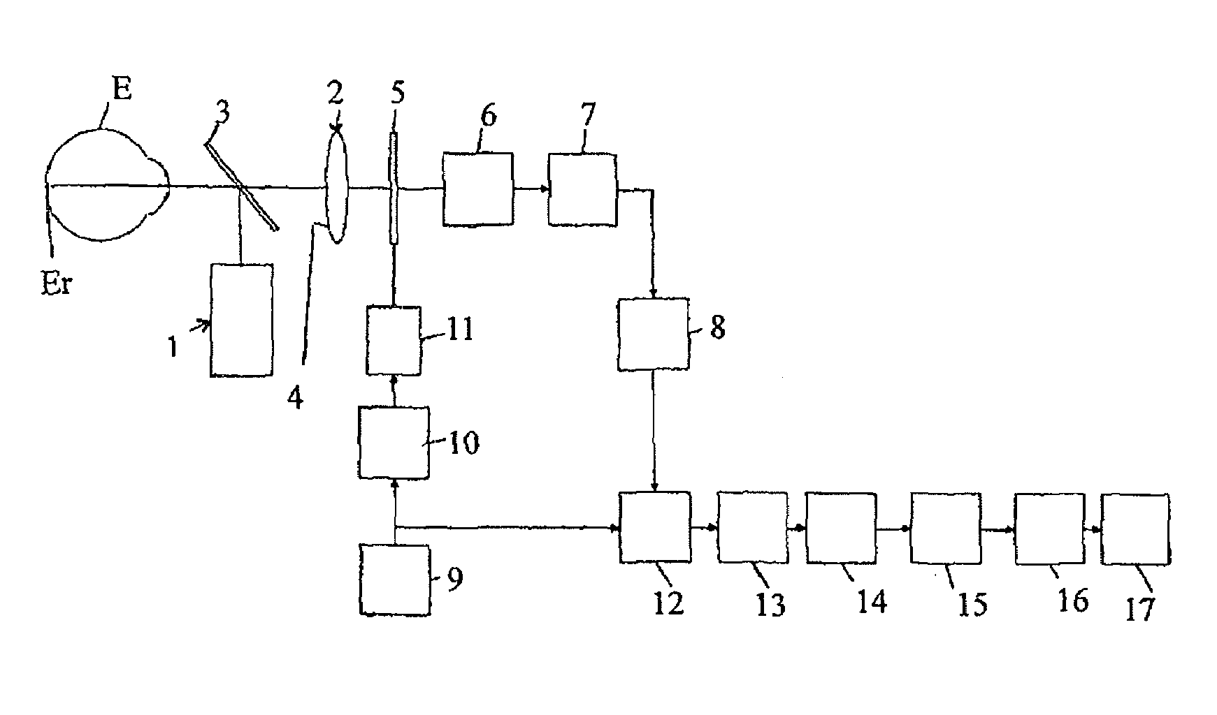
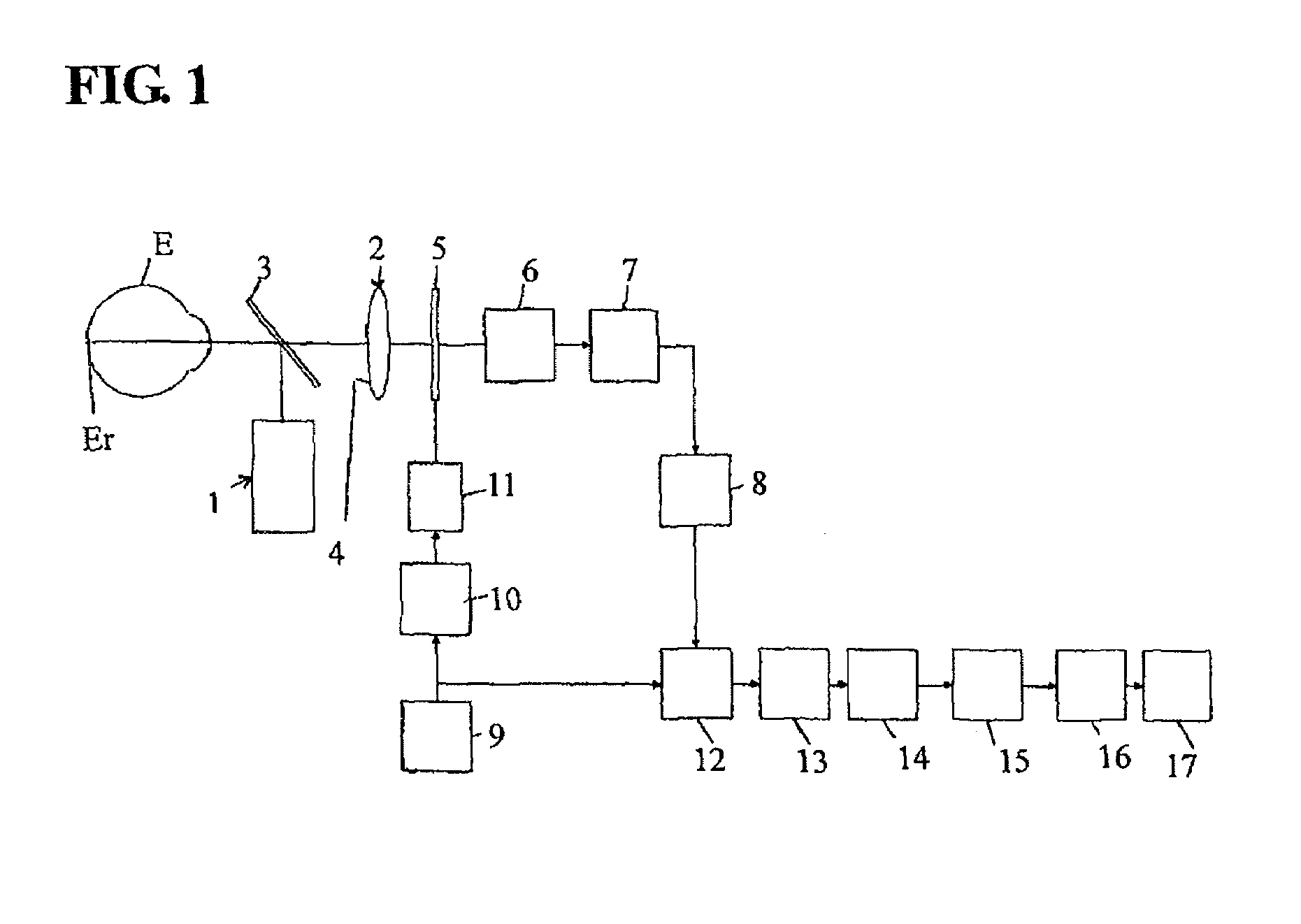
[0035]Hereinafter, the present invention will be described with reference to the drawings. FIG. 1 shows an overview of an optical system of the constitutions of a blood flow rate imaging device of the present invention; reference numeral 1 is a laser beam irradiation system, reference numeral 2 is a light receiving system, and E is a subject's eye. The laser beam of the laser beam irradiation system 1 is irradiated, for example, to an eye ground Er as a biological tissue of a subject's eye E, for example, via a half mirror 3.

[0036]The light receiving system 2 has a light receiving lens 4, CCD (solid state image sensor) 5 as a light receiver, and an amplifier circuit 6. Laser reflected light from eye ground Er is imaged to CCD 5 as a biological tissue image by the light receiving lens 4. CCD 5 has many pixels on its light receiving face, converts a biological tissue image imaged by the light receiving lens 4 into an electric signal, reads a signal charge by a frame storage system and...


PUM


Abstract

Provided is a blood flow rate imaging device that can automatically distinguish an artery and a vein from a blood flow rate obtained on a time series blood flow map. A blood flow rate imaging device of the present invention includes a laser beam irradiation system (1) that irradiates a laser beam to a biological tissue that has a blood cell, a light receiving system (2) that has a light receiver (5) including many pixels that detect reflected light from the biological tissue, an image capture section (12) that continuously captures a plurality of images for a predetermined time of one or more cardiac beats on the basis of signal from the light receiver (5), an image storage section (15) that stores a plurality of images, and an arithmetic section (16) that calculates a blood flow rate within a biological tissue from the time variation of the output signal of each pixel corresponding to a plurality of stored images, wherein the above arithmetic section has a detecting section that detects an artery and a vein from a plurality of images of the above one or more cardiac beats and displays an arterial pulse part and a venous pulse part on the blood flow map.

Description

TECHNICAL FIELD [0001]The present invention relates to a blood flow rate imaging device for measuring and imaging a blood flow rate on the basis of a speckle signal reflected from a biological tissue obtained by irradiating the biological tissue having blood cells with a laser beam.BACKGROUND ART [0002]A blood flow rate measuring instrument is conventionally known that irradiates with a laser beam a biological tissue having blood cells such as an eye ground of a subject's eye, introducing images formed by reflected light from the blood cells onto an image sensor such as a solid-state image sensor (CCD or CMOS), sequentially captures and stores a large number of these images at predetermined time intervals, selects a predetermined number of images from the large number of the stored images, calculates a value obtained by accumulating amounts of time variation of output in each pixel of each image and then calculates the velocity of blood cells (blood flow rate) from the value. In add...

Claims


Application Information

Patent Timeline
IPC IPC(8): A61B5/0265
CPCA61B3/1241G01F1/00G01P5/26G01P5/001G01F1/704
Inventor FUJII, HITOSHIOKAMOTO, KENJIFUJISAWA, KIMIHIKO
Owner SANGAKU RENKEI KIKO KYUSHU KK
Why Eureka
Try Eureka