System and method for joint resurfacing with dynamic fixation

a dynamic fixation and joint technology, applied in the field of joint resurfacing devices and systems for repairing defects in the joints, can solve the problems of partial arthroplasty procedure, damage to a portion of the native articulating surface, and reduce the natural ankle kinematics, and achieve the effect of accurate positioning of the drill guid

Inactive Publication Date: 2010-03-04
EXTREMITY MEDICAL
View PDF5 Cites 119 Cited by
  • Summary
  • Abstract
  • Description
  • Claims
  • Application Information

AI Technical Summary

Benefits of technology

[0010]Another object of the present invention is to provide a novel and useful joint resurfacing device for restoring the articulating surface of the talus through a minimally invasive procedure.
[0011]Another object of the present invention is to restore the articulating surface through minimal distraction of the joint.
[0015]Another object of the invention is to provide a means by which the ankle can be repaired via resurfacing the talar surface and then, in a modular manner, adding the tibial surface at a later date, if necessary.
[0018]In a third non-limiting aspect of the present invention, a system for resurfacing a joint in a foot is provided. The system comprises an implant device for replacing damaged tissue at the talus, a trial inserter assembly and a guide assembly. The implant device includes a generally curved member having a lateral portion and a distal portion. The implant device has an exterior surface provided to be slidably coupled to a tibial joint. The implant also comprises an inferior surface having an osteoconductive material, thereby causing the implant device to be selectively coupled to a talar dome.
[0019]In a fourth non-limiting aspect of the present invention, a system for resurfacing a joint in a foot is provided. The system comprises an implant device for replacing damaged tissue at the talus, a trial inserter assembly and a guide assembly. The implant device includes a generally curved member having a lateral portion and a distal portion. The implant device has an exterior surface provided to be slidably coupled to a tibial joint. The implant also comprises an inferior surface having fins or spikes, thereby causing the implant device to be selectively coupled to a talar dome.
[0020]In a fifth non-limiting aspect of the present invention, a method for resurfacing a joint in a foot is provided. First, a mid-foot incision is made in the foot. The talus in then prepared for restoration by distracting the tibial-talar joint and the damaged tissue is removed from the surface of the talus. Next, a trial inserter assembly is used to assist the surgeon in achieving the proper depth and alignment of implant device. After the correct trial-sized device has been determined, the surgeon will position the trial-sized device onto the talus and selectively couple guide assembly to the trial-sized device for accurate positioning of a drill guide. A guide wire is then installed and a hole is drilled in the talus using the guide wire. Following, an implant inserter is used to thread into the implant device. Once the implant device is installed, the threaded rod is pulled back through the tunnel until the implant device comes into contact with the talus. Next, the implant inserter is removed and a dynamic fixation device is inserted for ridged connection to the implant device using a screwdriver.

Problems solved by technology

However, these aforementioned procedures commonly reduce the natural ankle kinematics.
Generally, a hemiarthroplasty results from only a portion of the native articulating surface being damaged and requiring a partial arthroplasty procedure.
However, this is currently limited within the human ankle due to the amount of bone that is removed to make space for the implant.
In addition, the means of fixation has been well documented as an issue with keeping the implant fixed to the bone where migration and settling issues have been prevalent.
Currently, there are only a few implants designed to aid in the correction of osteocondral lesions and severe ankle arthritis without performing arthroplasty or arthrodesis.
This arthroscopic process is limited to removal of large defects and replaced with autograph or allograph cartilage taken from a donor site.
Also, ankle fusion and total joint replacement are aggressive procedures with difficult revision options and are therefore typically reserved for late stage disease.
In the ankle, there are few, if any, options for early surgical treatment that preserves the option for fusion, partial and total joint replacement, should they become necessary at a later time.

Method used


Image

  • System and method for joint resurfacing with dynamic fixation
  • System and method for joint resurfacing with dynamic fixation
  • System and method for joint resurfacing with dynamic fixation

Examples


Embodiment Construction

[0036]The present invention may be understood more readily by reference to the following detailed description of preferred embodiment of the invention. However, techniques, systems and operating structures in accordance with the present invention may be embodied in a wide variety of forms and modes, some of which may be quite different from those in the disclosed embodiment. Consequently, the specific structural and functional details disclosed herein are merely representative, yet in that regard, they are deemed to afford the best embodiment for purposes of disclosure and to provide a basis for the claims herein, which define the scope of the present invention. It must be noted that, as used in the specification and the appended claims, the singular forms “a”, “an”, and “the” include plural referents unless the context clearly indicates otherwise.

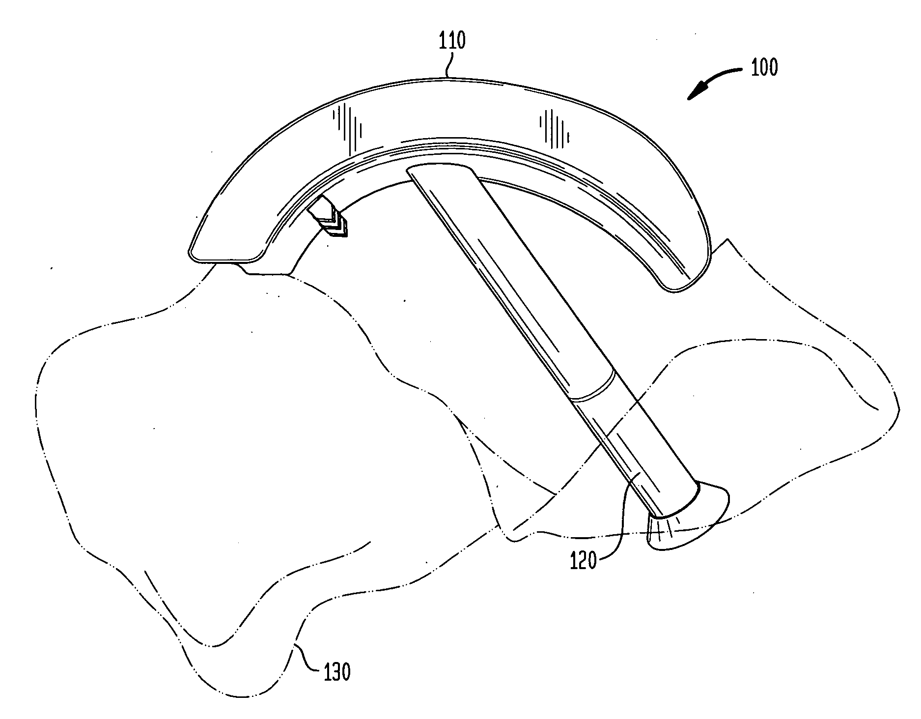
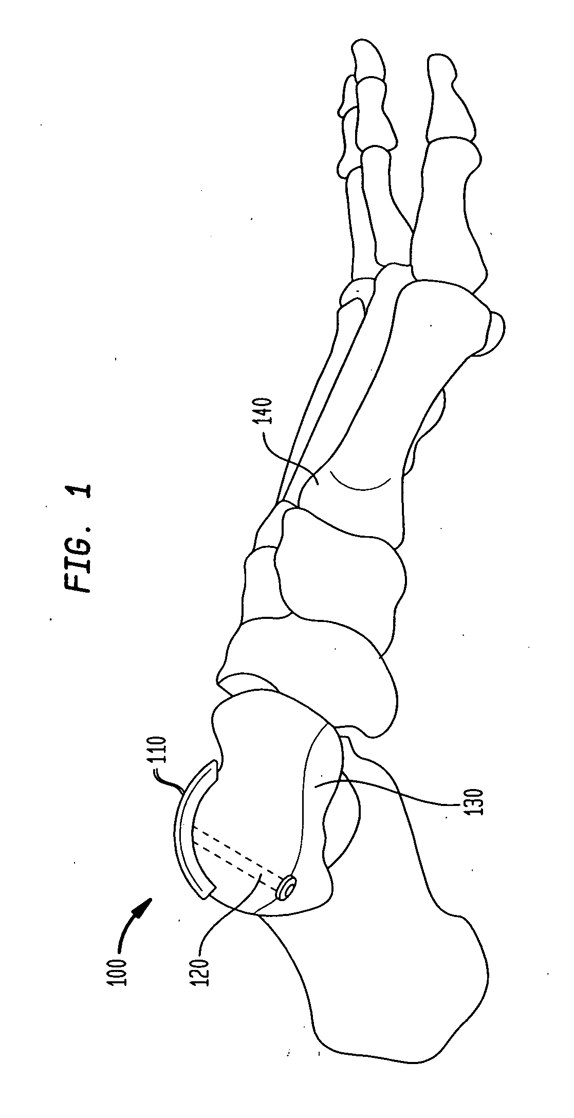
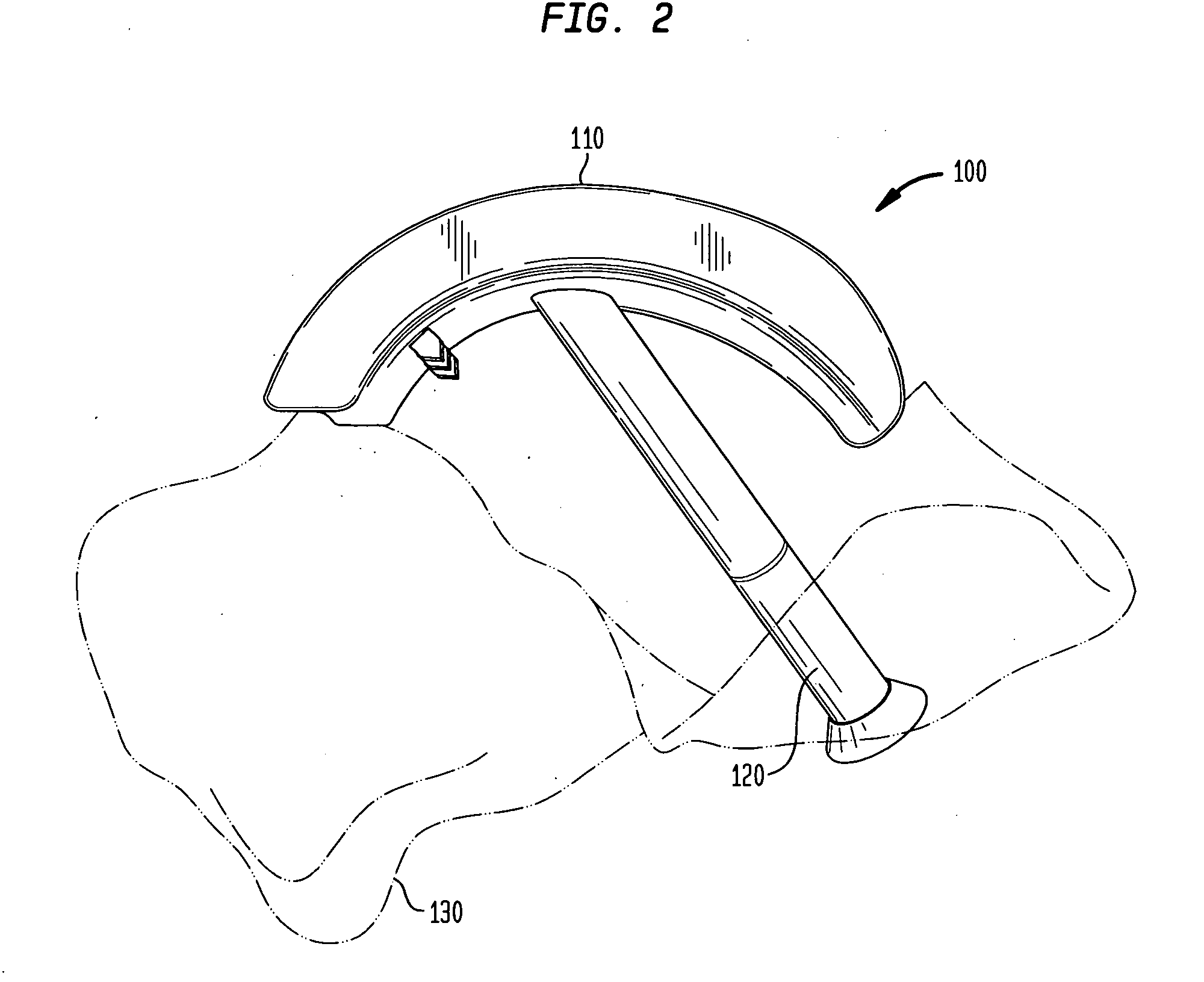
[0037]Referring now to FIGS. 1 and 2, there is shown a joint resurfacing system 100 in accordance with the teachings of the preferred emb...


PUM


Abstract

A joint resurfacing system for repairing defects in the articular surface of bones in the foot. The system includes a hemiarthroplasty implant for the talus resulting in minimal removal of the underlying bone. The implant device comprises a first curved surface and a second curved surface, with the second curved surface coupled to an articular surface of a talus bone via a dynamic fixation device.

Description

CROSS-REFERENCE TO RELATED APPLICATION[0001]This application claims the benefit of Provisional Application No. 61 / 135,715, filed Jul. 23, 2008, the entire contents of which are herein incorporated by reference.FIELD OF THE INVENTION[0002]This invention relates to the field of joint prosthesis, and more particularly, to a joint resurfacing device and system for repairing defects in the articular surface of bones in the foot.BACKGROUND OF THE INVENTION[0003]The talus is located in the center of the ankle and is primarily responsible for load transfer from the tibia through the entire foot. The talus is one of the main load bearing articulating surfaces within the human ankle and is commonly the location of ankle pain. Ankle pain is commonly associated with the presence of osteochondral lesion and joint arthritis. There are several methods of relieving ankle pain that range from non-surgical approaches to arthroscopic and surgical procedures. One cause of ankle pain is the location of ...

Claims


Application Information

Patent Timeline
Patent Type & Authority Applications(United States)
IPC IPC(8): A61F2/42A61B17/86A61B17/56
CPCA61F2/4202A61F2/4606A61F2/4684A61F2002/30878A61F2002/30892A61B2017/1775A61F2310/00017A61F2310/00023A61F2310/00029A61F2310/00071A61F2002/4207A61B17/1775
Inventor GANNOE, JAMYTYBER, JEFF
Owner EXTREMITY MEDICAL
Why Eureka
Try Eureka