Electronic Timepiece and Time Difference Correction Method for an Electronic Timepiece

Active Publication Date: 2010-03-04
SEIKO EPSON CORP
View PDF8 Cites 17 Cited by
  • Summary
  • Abstract
  • Description
  • Claims
  • Application Information

AI Technical Summary

Problems solved by technology

However, if the signal reception level is too low, the orbit information cannot be correctly demodulated and the position can therefore not be calculated.
However, if the location of the GPS satellite used for the positioning calculation is poor, the positioning calcula

Method used


Image

  • Electronic Timepiece and Time Difference Correction Method for an Electronic Timepiece
  • Electronic Timepiece and Time Difference Correction Method for an Electronic Timepiece
  • Electronic Timepiece and Time Difference Correction Method for an Electronic Timepiece

Examples


embodiment 1

2-1 Embodiment 1

Configuration of a GPS Wristwatch

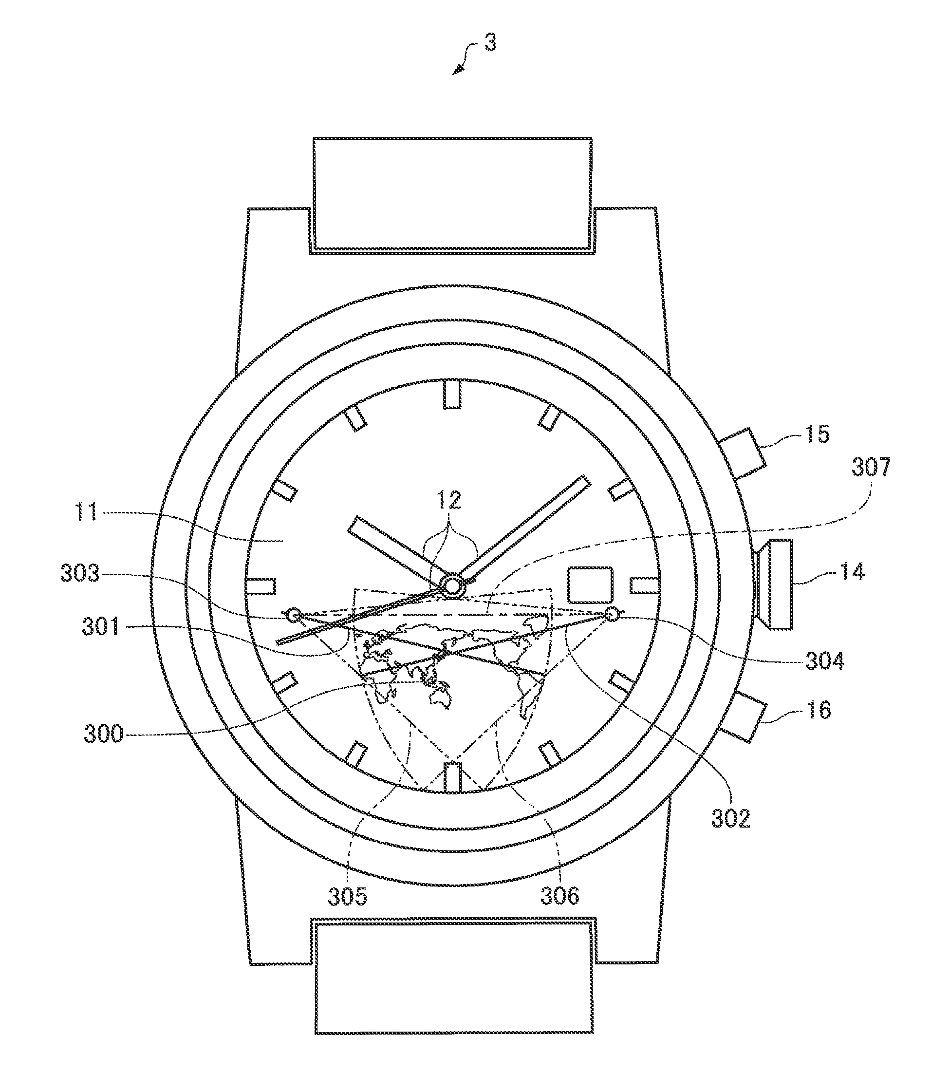
[0078]FIG. 3A and FIG. 3B are figures describing the configuration of a GPS wristwatch according to a preferred embodiment of the invention. FIG. 3A is a schematic plan view of a GPS wristwatch, and FIG. 3B is a schematic section view of the GPS wristwatch in FIG. 3A.

[0079]As shown in FIG. 3A, the GPS wristwatch 1 has a dial 11 and hands 12. A display 13 is disposed in a window formed in a part of the dial 11. The display 13 may be an LCD (liquid crystal display) panel, and is used to display information such as the current latitude and longitude or the name of a city in the current time zone or location, or other message information. The hands 12 include a second hand, minute hand, and hour hand, and are driven through a wheel train by means of a stepping motor.

[0080]The dial 11 and hands 12 function as a time information display unit in the invention in a preferred embodiment of the invention. The display 13 functions as a positioni...

embodiment 2

2-2 Embodiment 2

[0166]As shown in FIG. 7, FIG. 8A, and FIG. 8B, each of the divided areas has a complicated shape in the foregoing first embodiment because the geographical information 100 is divided along time zone boundaries. A large amount of data is therefore needed to define the boundary lines in the first embodiment, thus requiring a large capacity storage device and possibly increasing the size of the wristwatch. Furthermore, because deciding whether or not the assumed positioning region includes a time difference boundary is complex, the decision is time consuming and power consumption can be expected to increase.

[0167]Therefore, in order to reduce the amount of time difference information (boundary line data), the geographical information 100 is divided into a plurality of regions of a constant size instead of along time zone boundaries, and the coordinates of each region and corresponding time difference data are stored as the time difference information in flash memory 66...

embodiment 3

2-3 Embodiment 3

[0208]FIG. 15 is a flow chart of a time difference adjustment process in a GPS wristwatch according to the third embodiment of the invention.

[0209]The time difference adjustment process shown in FIG. 15 is basically the same as the time difference adjustment process shown in FIG. 6. More specifically, steps S10 to S44 in the time difference adjustment process shown in FIG. 15 are identical to steps S10 to S44 in the time difference adjustment process shown in FIG. 6, are therefore identified by the same reference numerals, and further description thereof is omitted.

[0210]The time difference adjustment process shown in FIG. 15 adds a step of displaying the assumed positioning region (the process in step S46) to the time difference adjustment process shown in FIG. 6. Note that this step of displaying the assumed positioning region (the process in step S46) may be executed before the step of adjusting the displayed time (the process of step S40).

[0211]FIG. 16 describes ...


PUM


Abstract

An electronic timepiece has a function for receiving satellite signals transmitted from positioning information satellites, and includes a reception unit that receives the satellite signal and acquires satellite information from the received satellite signal, a satellite search unit that executes a process of searching for a capturable positioning information satellite based on the received satellite signal and capturing the found satellite signal, a positioning calculation unit that selects a specific number of positioning information satellites from among the positioning information satellites captured by the satellite search unit, executes a positioning calculation based on the satellite information contained in the satellite signals sent from the selected positioning information satellites, and generates positioning information, a time information adjustment unit that corrects internal time information based on the satellite information, a time information display unit that displays the internal time information, a storage unit that stores time difference information defining the time difference in each of a plurality of areas into which geographical information is divided, and a time difference evaluation unit that calculates an assumed positioning region based on the positioning information, and determines based on the time difference information if the assumed positioning region contains a time difference boundary. The time information adjustment unit correcting the internal time information based on the time difference in the assumed positioning region when the time difference evaluation unit determines that the assumed positioning region does not contain a time difference boundary, The positioning calculation unit reselecting the specific number of positioning information satellites and continuing the positioning calculation when the time difference evaluation unit determines that the assumed positioning region contains a time difference boundary. The reception unit terminates satellite signal reception when the time difference evaluation unit determines that the assumed positioning region does not contain a time difference boundary.

Description

CROSS-REFERENCE TO RELATED APPLICATIONS[0001]Japanese Patent Application No (s) 2008-227058 and 2008-249943 are hereby incorporated by reference in their entirety.BACKGROUND[0002]1. Field of Invention[0003]The present invention relates to an electronic timepiece and to a time difference correction method for an electronic timepiece that corrects the time difference based on satellite signals received from positioning information satellites such as GPS satellites.[0004]2. Description of Related Art[0005]The Global Positioning System (GPS) in which satellites (GPS satellites) orbiting Earth on known orbits transmit signals carrying superposed time information and orbit information, and terrestrial receivers (GPS receivers) receive these signals to determine the location of the receiver, is widely known. Electronic timepieces that acquire accurate time information (“GPS time”) from GPS satellites and adjust the current internally kept time to the correct time have also been developed a...

Claims


Application Information

Patent Timeline
IPC IPC(8): G01S1/00G01C21/00G04G5/00G04R20/04G04R20/06
CPCG04G5/002G04R20/06G04R20/04
Inventor AKIYAMA, TOSHIKAZU
Owner SEIKO EPSON CORP
Why Eureka
Try Eureka